TROUBLESHOOTING AND ELECTRICAL SYSTEM: FE400, KEY-START ENGINE
Test Procedures
Page 11-20
2006-2010 Turf/Carryall 272/472 and XRT 1200/1200 SE Maintenance and Service Manual
11
Test Procedure 8 – Starter/Generator (Starter Function), Continued:
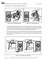
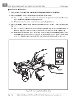
8. With the wires still disconnected, using a multimeter set to 200 ohms, place the red (+) probe on the DF
terminal and the black (–) probe on the F1 terminal. The reading should be between 4.5 and 5.5 ohms.
If the reading is incorrect, a possible grounded DF terminal and/or grounded field coil may be the cause.
The starter/generator will need to be removed from the vehicle and disassembled by a qualified techni-
cian.
See Starter/Generator Removal, Section 12, Page 12-1.
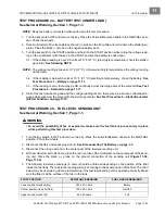
TEST PROCEDURE 9 – WIRE CONTINUITY
See General Warning, Section 1, Page 1-1.
1. Turn the key switch OFF and remove the key. Place the Forward/Reverse handle in the NEUTRAL posi-
tion. Chock the wheels.
2. Disconnect battery and spark plug wire(s).
See Disconnecting The Battery on page 1-3.
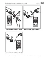
3. To test a wire for continuity, disconnect either end from the electrical component it is attached to.
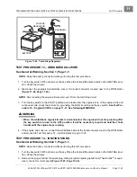
4. Set the multimeter to 200 ohms and place the red (+) probe on the terminal at one end of the wire. Place
the black (–) probe on the other terminal end of the wire. The reading should be continuity. If the reading
is incorrect, repair or replace the wire.
TEST PROCEDURE 10 – DIODE (GENERATOR CIRCUIT)
See General Warning, Section 1, Page 1-1.
1. Turn the key switch OFF and remove the key. Place the Forward/Reverse handle in the NEUTRAL posi-
tion. Chock the wheels.
2. Disconnect battery and spark plug wire(s).
See Disconnecting The Battery on page 1-3.
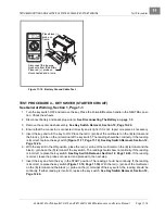
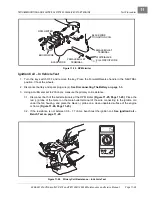
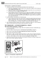
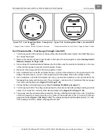
3. Disconnect the red and white wires of the diode assembly from the solenoid posts, located within the
electrical component box.
3.1. Remove the intake hose to the carburetor at the carburetor intake port and move the hose to allow
easy access to the electrical component box cover.
3.2. Remove the cover retaining screw (5) and electrical component box cover (6)
.
3.3. Remove the locknuts (7) from the two large solenoid posts and disconnect the diode wires from the
solenoid.
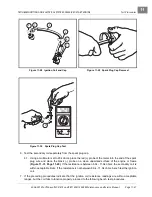
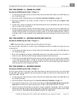
4. With the multimeter set to the diode test function (
ç
), connect the black (–) probe of the multimeter to
the white lead of the diode and the red (+) probe of the multimeter to the red lead of the diode
. The reading should indicate an overload (no continuity). A diode is
designed to conduct current in one direction only. If a diode conducts current (shows continuity) with the
meter probes as described, the diode has failed and must be replaced.
5. Reverse the multimeter probes and note the reading. With the black (–) probe of the multimeter to the
red lead of the diode and the red (+) probe of the multimeter to the white lead, the meter should read
approximately 450 mV, however, a range of 400-500 mV is acceptable
6. Connect either the black (–) or red (+) lead of the multimeter to the diode body (case). Connect the other
multimeter lead to both the red and white lead terminals of the diode. The multimeter should indicate an
overload, (no continuity). If continuity reading does occur, it indicates that one or both of the diode leads
are grounded to the diode body (case) and the diode must be replaced.
7. If the diode tests good, reconnect the diode leads.
See Diode Installation, Section 12, Page 12-22.
See also following WARNING.
Summary of Contents for CARRYALL 272
Page 2: ......
Page 14: ......
Page 18: ...1...
Page 52: ...5...
Page 90: ...6...
Page 110: ...7...
Page 112: ...8...
Page 128: ...10...
Page 170: ...11...
Page 224: ...13...
Page 284: ...16...
Page 302: ...17...
Page 308: ......
Page 309: ...Club Car R NOTES...
Page 310: ...Club Car R NOTES...
Page 311: ......

