Clover Z670 Instruction Manual Download Page 6

▪ 

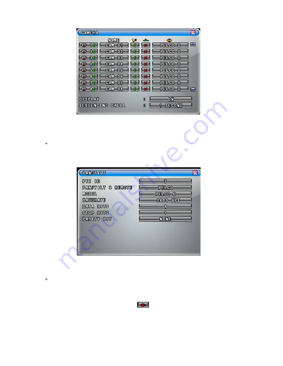
Click the “PAN/TILT (PELCO D)” button on the channel you wish to install the

zoom camera and then the PAN/TILT Menu will be displayed as shown in Fig.4-5.


▪  

Settings in the PAN/TILT Menu


(Refer to System manual section 7-4.5 on page 90 for more detail)

- Click the PTZ ID button in the PAN/TILT Menu shown in Fig.4-5, then the On

    Screen Keyboard will show up. 

- Delete the current PTZ ID with the

button and enter a new ID by using On

Screen Keyboard, and then click “

OK”

button to set with the new ID. The ID

should be the same ID as the zoom camera has (e.g.: If the ID of the zoom camera

is set to 7, the PTZ ID in the PAN/TILT Menu as shown in Fig.4-5 should be

entered 7).

[Fig.4-4 Camera Menu]

[Fig.4-5 PAN/TILT Menu]

Summary of Contents for Z670

Page 1: ...INSTRUCTION MANUAL 30X DAY NIGHT ZOOM CAMERA MODEL Z670 Copyright 2009 Clover Inc All Rights Reserved...

Page 2: ...t away from strong magnetic fields Do not expose this product in direct sunlight or strong reflected rays Refer servicing to qualified personnel only Do not change or modify this product the warranty...

Page 3: ...has a terminal block for 2 wires in polarity Connect the provided twisted pair cable to this terminal block and the other end to the DVR system refer to Chapter 5 0 Installation for more detail 6 Men...

Page 4: ...is selected the zooming function will be operated properly If the OFF is selected the zooming function won t be working LOCK Choose LOCK in the Menu shown in Fig 4 1 by pressing TELE WIDE button and s...

Page 5: ...the ON is selected and the normal image when the OFF is selected BAUD RATE Choose BAUD in the Menu shown in Fig 4 2 by pressing TELE WIDE button and choose 2400 BPS Bit Per Second among 2400 4800 and...

Page 6: ...ck the PTZ ID button in the PAN TILT Menu shown in Fig 4 5 then the On Screen Keyboard will show up Delete the current PTZ ID with the button and enter a new ID by using On Screen Keyboard and then cl...

Page 7: ...nals on the rear of the camera and the DVR system as shown in Fig5 1 Refer to the instruction manual of DVR system relevant to the location of and terminals for RS485 To connect the bared copper wire...

Page 8: ...em is turned ON for the next step Attach the mounting bracket to the desired location on the wall or ceiling wherever you want to install the zoom camera Locate a wall stud or ceiling joist and secure...

Page 9: ...e R d n a s e s u a C s m e l b o r P n e e w t e b e l b a c 0 6 f o n o i t c e n n o c k c e h C e r u t c i p o N the DVR system and the camera Check the included AC power supply for retail packag...

Page 10: ...supply DC 12V Operational temperature 10 C to 50 C RH95 Max Dimensions 60 W x 60 H x 120 L mm Weight 0 9 Lbs 1 Zoom camera 1 Mounting bracket 1 60 6pin Din cable for COM22168 Not included in the retai...

Page 11: ...tions on incidental or consequential damages Original purchaser must fill out the warranty card and mail it to the factory with the model number serial number and the date of purchase We will repair o...

Reviews: