


1. Before mounting any blade on the saw: the blade should be inspected for any
damage which might have occurred during shipment, handling or previous use.
2. The blade collars and arbors should be cleaned and examined for damage before
mounting the blade.
3. The blade must be properly fitted over the arbor with the drive pin on the outside
collar projecting through the drive pin hole on the blade and inside collar.
4. The blade shaft bolt which is a left hand thread bolt on the operator’s right hand
side and right hand thread on the operator’s left hand side must be tightened
securely against the outside blade shaft collar.
5. The blade must be operated within the specified maximum operating speed listed
on the blade.
6. Turn water control valve to full to provide adequate coolant (5 to 8 gallons per
minute) for diamond blades and wet cutting abrasive blades. Insufficient coolant
could result in severe blade breakage or diamond segment separation.
7. The blade guard must be in place with the nose guard down and locked when the
saw is running.
8. The operator should wear safety glasses and any other appropriate safety
equipment.
9. When starting the saw, the operator should stand away and to the side of the blade.
10. If for any reason the saw should stall in the cut, raise the blade out of the cut.
Check the outside blade shaft collar and nut for tightness. Inspect the blade for
damage before restarting the saw. Use caution when resuming a cut. Be certain
that the blade is in alignment with the previous cut.
11. During cutting operations do not exert excess side pressure on the handles as a
method of steering. Do not force the blade into the cut by lowering the blade too
fast or by pushing the saw too fast.
You Are Responsible For Your Safety!!!
C-65B PAVEMENT SAW OPERATING INSTRUCTIONS
Summary of Contents for C65B
Page 1: ...OWNER S MANUAL CONCRETE SAW MODEL C65B FORM 5313 12 03 01 ...
Page 9: ...C65B MAIN FRAME GROUP ...
Page 12: ......
Page 14: ......
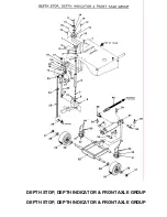
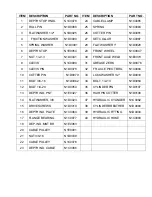
Page 17: ...DEPTH STOP DEPTH INDICATOR FRONT AXLE GROUP DEPTH STOP DEPTH INDICATOR FRONT AXLE GROUP ...
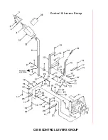
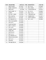
Page 19: ...C65B CONTROL LEVERS GROUP ...
Page 21: ......
Page 23: ...C65B PARTS LIST BLADE SHAFT DRIVES GROUP ITEM DESCRIPTION PART NO ITEM DESCRIPTION PART NO ...
Page 25: ......
Page 27: ......
Page 29: ......
Page 31: ......
Page 33: ......
Page 34: ......
Page 35: ......
Page 36: ......
Page 39: ...NOTES ...


