2.6
FITTING THE CASING
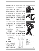
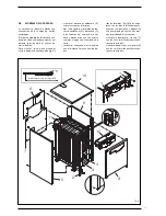
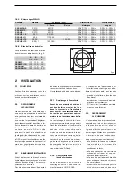
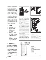
The casing and the control panel are
supplied in separate cardboard packa-
ges. The housing package also con-
tains the boiler documents and the
glass wool for insulating the cast iron
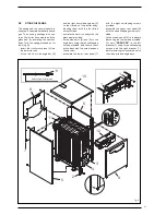
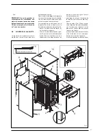
body. To fit the casing, proceed as fol-
lows (fig. 8):
– insert the front crosspiece (4) into
the lower tie-rods;
– fix the left front side angle bar (2)
and the right front side angle bar (3)
to the tie-rods of the boiler body,
blocking them with the four blind
nuts provided;
– insulate the cast iron body with the
glass wool provided;
– fix the side parts (5) and (6) to the
angle bars using the ten self-tapping
screws provided, and secure them
at the back with the nuts placed on
the tie rods;
– assemble the lower rear panel (7)
with the eight self-tapping screws
provided;
– assemble the upper rear panel (8)
with the six self-tapping screws pro-
vided;
– fix the control panel (12) to the angle
bars using the four screws provided.
For vers.
“GG GHP 2S”
, fix the left
bracket (1) using three self-tapping
screws and the right bracket (1),
before installing the control panel, to
the side parts and angle bars;
27
4
2
3
5
6
7
8
12
11
10
9
Sonda termostato sicurezza
11
1
1
Fig. 8
Safety thermostat probe
Summary of Contents for GG GHP 2S
Page 1: ...GG GMP 2S GG GHP 2S IT ES ENG FR RO RUS ...
Page 63: ......

