P/N 102615, Rev. 0
Page 37
Engraved markings on the clamp collar enable setting
angles within ±0.5°.
3.4.7
Adjusting the feed
NOTICE
The feed unit can be placed on either the radial or
axial slides depending if the machining operation is
facing or boring.
Do the following to adjust the feed:
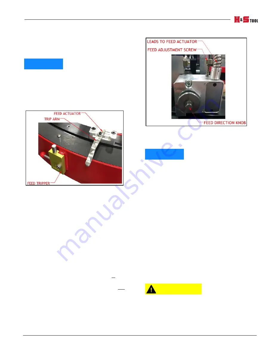
1. Install the feed trippers as required (see Figure
3-12).
F
IGURE
3-12. F
EED
TRIPPER
LOCATION
T
IP
:
The number of feed trippers determines the
feed rate and desired finish. Four feed
trippers are included. The feed box is
adjustable from 0.001–0.008" (0.025–0.2 mm)
of revolution per trip. Finer finishes typically
use one or two feed trippers with the feed
adjustment set small per trip. Coarse or
faster finishes use all four feed trippers.
2. Set the feed direction according to the follow-
ing steps, as shown in Figure 3-13:
a) Push the feed direction knob in to feed
the tool away from the feed box.
b) Pull out the feed direction knob out to
feed the tool toward the feed box.
T
IP
:
It may be necessary to slightly twist the knob
when changing the feed direction.
F
IGURE
3-13. F
EED
ADJUSTMENTS
3. Set the feed amount per trip.
NOTICE
When the feed adjustment screw is unscrewed the
maximum amount, feed is at the maximum amount
of approximately 0.008" (0.2 mm) per trip. When
the feed adjustment screw is screwed in, the feed is
at the minimum. Adjusting the thumb screw will
change the angle of the trip arm on the feed
actuator.
4. Route and secure the feed cable to prevent it
from kinking or catching on any obstructions.
3.4.8
Installing the drive
There are four options for drive motor. The ODF30
through ODF70 use a standard pneumatic or hydraulic
motor with a 3/4" (19.0 5mm) shaft. The ODF80 through
ODF120 use a larger pneumatic or hydraulic motor with
a 1" (25.4 mm) shaft.
Red-blue labels (P/N 60219, 60220 shown in Table 1-4
on page 5) on either side of the machine that the drive
motor is installed on shows the hose arrangement for
correct motor run direction.
CAUTION
Pay careful attention to the machine direction and
hose connections. If the machine is run opposite to
the rotation direction, the feed tripper may be
damaged. The correct direction is clockwise when
viewed from above the bridge.
Summary of Contents for H&S TOOL SPEED FACER ODF100
Page 2: ......
Page 4: ...Page B ODF Speed Facer Operating Manual CLIMAX GLOBAL LOCATIONS ...
Page 5: ...P N 102615 Rev 0 Page C CE DOCUMENTATION ...
Page 6: ...Page D ODF Speed Facer Operating Manual CE DOCUMENTATION ...
Page 8: ...Page F ODF Speed Facer Operating Manual This page intentionally left blank ...
Page 11: ...P N 102615 Rev 0 Page iii TABLE OF CONTENTS CONTINUED CHAPTER SECTION PAGE APPENDIX B SDS 111 ...
Page 12: ...Page iv ODF Speed Facer Operating Manual This page intentionally left blank ...
Page 16: ...Page viii ODF Speed Facer Operating Manual This page intentionally left blank ...
Page 18: ...Page viii ODF Speed Facer Operating Manual This page intentionally left blank ...
Page 62: ...Page 44 ODF Speed Facer Operating Manual This page intentionally left blank ...
Page 106: ...Page 88 ODF Speed Facer Operating Manual FIGURE A 28 ODF120 SPEED FACER ASSEMBLY P N 7639 S1 ...
Page 107: ...P N 102615 Rev 0 Page 89 FIGURE A 29 ODF120 SPEED FACER LABEL LOCATIONS P N 89210 ...
Page 123: ...P N 102615 Rev 0 Page 105 FIGURE A 45 HYDRAULIC DRIVE MOTOR ASSEMBLY P N 91110 ...
Page 126: ...Page 108 ODF Speed Facer Operating Manual FIGURE A 48 CABLE PROTECTION COMPONENTS ...
Page 128: ...Page 110 ODF Speed Facer Operating Manual This page intentionally left blank ...
Page 130: ...Page 112 ODF Speed Facer Operating Manual This page intentionally left blank ...
Page 131: ......
Page 132: ......


