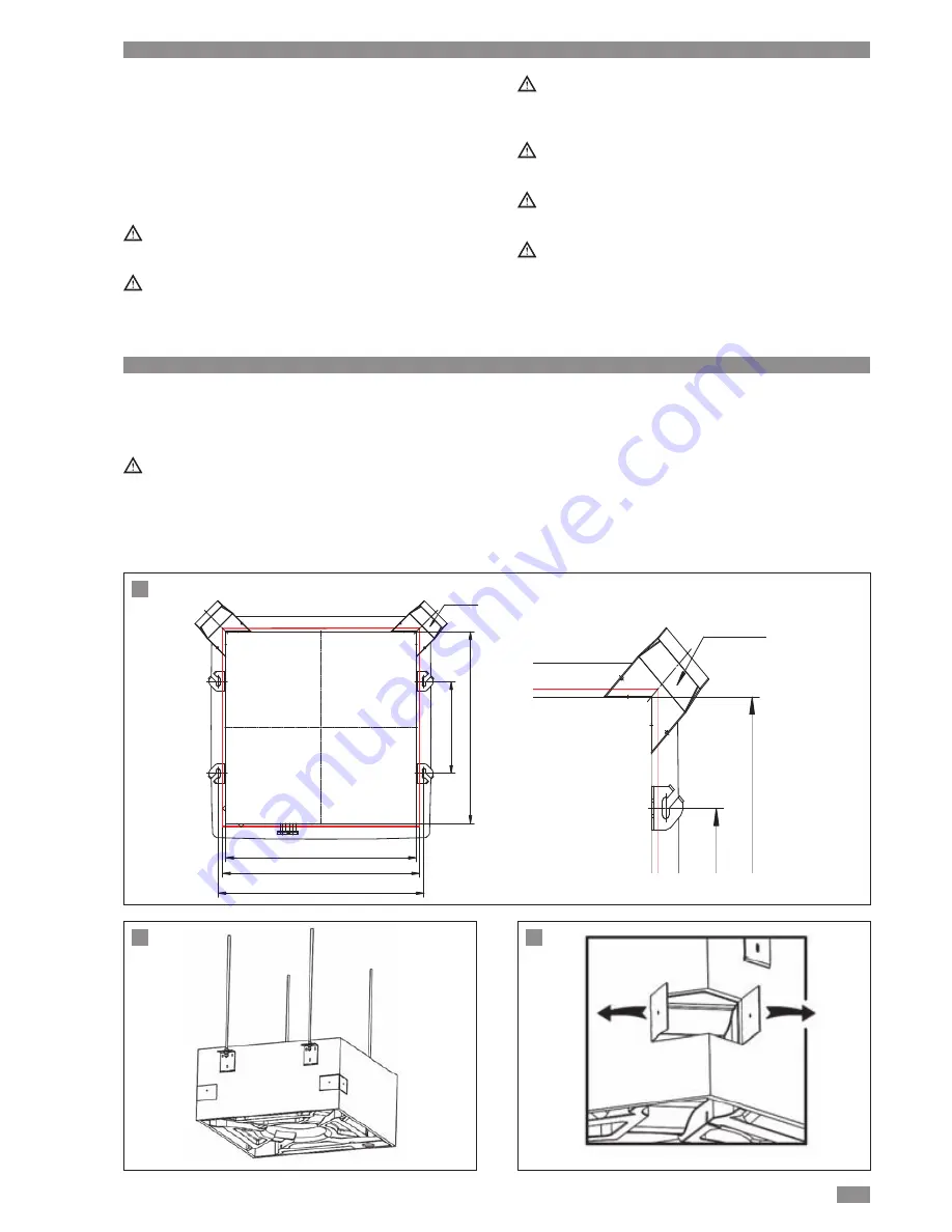
CLIMAVENETA a-CHD U-2T 606+2209 Operating And Installation Manual Download Page 15

15

EN

Fresh air flange
(optional)

Fresh air flange
(optional)

580 mm

280 mm

580 mm

600x600 mm

632 mm

1

2

3

• To install the valves, see the instructions shown on the

valve kit instruction sheet. To make the connection to the
Cassette, please make reference to the unit drawings.

• In cold water installation, to avoid that the condensate

drops on the ceiling, it is necessary to insulate the piping,
the valves, and the coil’s connections.

• For valves electric connection refer to wiring diagram relat-

ed to selected control.

The cables must pass through the apposite fairleads and
flexible couplings.

The valves must be connected according to the suggest-
ed electric wiring diagrams.

If the proposed connections are not respected, there will
be the risk that the water overflows from the condensate
collection tray.

It is important that the valves open only when the fan is
working at one of the three speeds.

Check the seal in the most critical points of the plant
when it is filled of liquid for the first time.

The manufacturer cannot be consider responsible in
case of bad working or damages due to the drop of
valves sets purchased directly by the installer from other
suppliers.

Fresh air change

CHD – cassette units have primary air flow connection. This
air is mixed with the untreated room air inside the appliance.

The pressure at the treated air inlets is slightly below
atmospheric pressure. The low pressure should be dis-
regarded in the design of the treated air system.

Fresh Air Renewal Connection

The fresh air system for cassette unit allows up to 15% of
unit airflow as fresh air intake (per connection). Maximum 2
fresh air connections per unit are allowed.
1. The corners of the cassette allow separate ductwork to

be installed for outside air intake (Figure 

1

).

2. Cut and remove thermal insulating material.
3. Open the mounting plate (Figure 

2

and Figure 

3

)

4. Install the flanges to casing and fix it with 2 screws.

Flange is rectangular duct with dimension 110 x 55mm.

INSTALLATION OF VALVE UNIT 

Installation

DUCT INSTALLATION 

Installation

Summary of Contents for a-CHD U-2T 606+2209

Page 1: ...OPERATING AND INSTALLATION MANUAL EN FAN COIL CASSETTE EN Please read this guide carefully before switching on the appliance MODELS a CHD U 2T 606 2209 a CHD U 4T 706 2209 i CHD U 2T 706 2209...

Page 2: ...uishing plastic Electric fan unit centrifugal fans coupled directly to the 5 speed electric motor Exchange coil consisting of copper pipes with swirl design and aluminium fins Air filter WALL MOUNTED...

Page 3: ...g storms put the installation on off switch to off This instruction booklet is an integral part of the appli ance and should therefore be carefully preserved and ALWAYS accompany the appliance also in...

Page 4: ...maged by temperatures below freezing point During installation for safety reasons observe the fol lowing precautions Always use work gloves The unit must always be handled by two people Fan coil units...

Page 5: ...stable for vertical airflow direction at two three and four way The air louvers can be controlled automatically See Louver control on p 22 All the main parts can be easily accessed through the grille...

Page 6: ...ver control on p 22 All the main parts can be easily accessed through the grille Regenerative air filters Accident prevention grille over the fan intake Double coil for four pipe installation Coils wi...

Page 7: ...tel G3 4 water outlet Drainage Drain hole for external drain pan Fresh Air Flange a CHD U 2T 1108 i CHD U 2T 1108 Mounting brackets 100 branch duct G3 4 water intel G3 4 water outlet Drainage Drain ho...

Page 8: ...nge G3 4 hot water outlet G3 4 chilled water outlet G3 4 hot water inlet G3 4 chilled water inlet a CHD U 4T 706 Mounting brackets 100 branch duct Drainage Drain hole for external drain pan Fresh Air...

Page 9: ...NGS General Mounting brackets 100 branch duct Drainage Drain hole for external drain pan Fresh Air Flange G3 4 hot water outlet G3 4 chilled water outlet G3 4 hot water inlet G3 4 chilled water inlet...

Page 10: ...W 1 11 2 15 2 96 5 52 Vel 4 kW 1 35 2 45 3 85 6 35 Vel 3 kW 1 62 2 85 4 37 7 37 Vel 2 kW 1 89 3 4 89 7 87 Vel 1 kW 2 5 3 17 5 06 8 21 Max water flow m3 h 0 55 0 78 1 19 2 01 Max pressure drop kPa 10 3...

Page 11: ...2 Sensible cooling capacity 1 Vel 5 kW 2 18 2 76 4 94 Vel 4 kW 2 43 3 77 5 37 Vel 3 kW 2 55 4 2 5 97 Vel 2 kW 2 7 4 33 6 05 Vel 1 kW 2 88 4 46 6 57 Max water flow m3 h 0 59 0 98 1 36 Max pressure drop...

Page 12: ...acteritics Water content l 1 56 1 78 2 41 Water inlet fittings inch 3 4 3 4 3 4 Water outlet fittings inch 3 4 3 4 3 4 Max adsorbed power W 40 88 200 Max adsorded current A 0 347 0 765 1 739 Electrica...

Page 13: ...ts without valve assembled Pressure loss Kpa l h 706 20 0 20 40 60 80 100 120 140 160 180 200 2 0 0 4 0 0 6 0 0 8 0 0 1 0 0 0 1 2 0 0 1 4 0 0 1 6 0 0 1 8 0 0 2 0 0 0 1108 2209 4 pipe units in COOLING...

Page 14: ...les in the ceiling using the template provided in the packaging also see the dimensional drawings Mark the position of the hangers on ceiling by using posi tion A B C D in the paper pattern Depending...

Page 15: ...most critical points of the plant when it is filled of liquid for the first time The manufacturer cannot be consider responsible in case of bad working or damages due to the drop of valves sets purcha...

Page 16: ...16 EN DUCT INSTALLATION Installation 4 6 5 Fresh Air Duct dimension mm...

Page 17: ...is shown by the drawings All air ducting departing from the fan coil unit must fea ture thermal insulation to avoid condensation and drip ping water After duct insulation complete the water and elect...

Page 18: ...ellow sticker on the casing for location of branch duct or fresh air intake connections 2 The sticker is at the center of a knock out hole under neath the casing insulation Use a cutter and follow alo...

Page 19: ...Drainage Drain hole for external drain pan G3 4 hot water outlet G3 4 chilled water outlet G3 4 hot water inlet G3 4 chilled water inlet a CHD U 4T 706 Drainage Drain hole for external drain pan G3 4...

Page 20: ...depth should be made to prevent unpleasant odours from reaching the room Maximum pump head is 500 mm from the bottom edge of the unit The condensate pipe must be insulated If more than one unit is ins...

Page 21: ...s The board has a terminal block for connecting the power supply speed management valve control and safety device The unit must always be earthed Upstream of the unit fit an Omni polar switch with min...

Page 22: ...tor power supply cables available on the unit accessible through the grill opening to the main terminal block in the electri cal box see Fig 1 2 3 Automatic louver control With the unit off control OF...

Page 23: ...23 EN ELECTRICAL CONNECTION Installation Mounting Front Panel Assembly 1 Remove return grille from front panel 2 Move the front panel to casing 3 Tighten 4 screws as shown in Figure 1 and Figure 2 1 2...

Page 24: ...RE BLUE NEUTRAL GREEN LOWEST RED LOW ORANGE MEDIUM BROWN HIGH YELLOW HIGHEST Ti2 Tr Pre wired sensor cable For use when connecting to S FULL CONTROL ATTENTION C65403162F EXTERNAL POWER SUPPLY 230VAC 1...

Page 25: ...c NOTE JUMPER S1 MUST BE CLOSED M6 A B iK EKW A B N Heating Valve Cooling Valve N FACTORY WIRING FIELD WIRING SA1 QM1 Green Red Grey Black Blue Orange Brown J3 NOTE CONNECT TS2 ONLY WITH 4 PIPE UNIT L...

Page 26: ...ve YVH Heating valve H N L V2 L V1 M 2 1 7 6 3 4 5 QM U N PE 230V 50Hz 12 13 SA1 TTL a CHD 606 2209 ATW MTW N YVE YVH 8 9 FIELD WIRING NOTE CONNECT YVH ONLY WITH 4 PIPE UNIT 26 EN ELECTRICAL CONNECTIO...

Page 27: ...ve YVH Heating valve H N L V2 L V1 M 2 1 7 6 3 4 5 QM1 U N PE 230V 50Hz 12 13 SA1 TTL i CHD 706 2209 ATW MTW N YVE YVH 8 9 FIELD WIRING NOTE CONNECT YVH ONLY WITH 4 PIPE UNIT 27 EN ELECTRICAL CONNECTI...

Page 28: ...VE Cooling valve YVH Heating valve H N L V2 L V1 M a CHD 606 2209 1 QM N U PE 230V 50Hz 2 1 7 6 3 4 5 12 13 TTL ATW MTW SA1 H N L V2 L V1 M a CHD 606 2209 2 H N L V2 L V1 M a CHD 606 2209 3 KAE KAH KA...

Page 29: ...VE Cooling valve YVH Heating valve H N L V2 L V1 M i CHD 706 2209 1 QM N U PE 230V 50Hz 2 1 7 6 3 4 5 12 13 TTL ATW MTW SA1 H N L V2 L V1 M i CHD 706 2209 2 H N L V2 L V1 M i CHD 706 2209 3 KAE KAH KA...

Page 30: ...1 Thermomagnetic switch SA1 Multifunction contact TS1 Water temperature sensor TS2 Water temperature sensor 2 YVE Cooling valve YVH Heating valve H N L V2 L V1 M L N EV1 EV2 V3 U N PE 230V 50Hz J2 i C...

Page 31: ...B terminal block i HB terminal block LEGEND iK Wall mounted Environment Thermostat iHB Electronic board QM1 Thermomagnetic switch 31 EN ELECTRICAL CONNECTION Installation Multiple connection cassette...

Page 32: ...0 C Storage temperature 20 C 85 C Max storage humidity 90 not condensing Working temperature 0 C 55 C Max working humidity 90 not condensing Protection rating IP 30 Case material PC ABS flame retardan...

Page 33: ...hot enough It is not available if the heating element is installed CONFIGURATION OF THE MTW CONTROL Analog inputs Air sensor input included in MTW control analog input used for temperature control Wa...

Page 34: ...ed Medium fan speed Minimum fan speed Automatic fan speed Led Blue LED Heating Cooling plus regulator call Blue LED blinking Hot start Too Cool function active Blue LED operation in Cooling mode Blue...

Page 35: ...he copper water pipe Digital outputs YV1 Valve control max 0 1 A This is used for opening the delivery valve and the conse quent water flow into the coil as described below 2 pipe system the valve con...

Page 36: ...ly given from the power board installed as standard on the side of the CHD Temperature selector Adjust the temperature as required by turning the temperature selector from 14 C to 30 C If connected as...

Page 37: ...available in the cooling mode but only acti vates the fan if the water in the coil is cold enough Failure display When the ventilation is inhibited by inadequate temperature mode of operation required...

Page 38: ...ion My Home Bticino Kit RS485 interface for Building Management System i CHD could be connected into centralized and supervision system via modbus protocol RS485 Kit RS485 is installed on i HB Power b...

Page 39: ...e fan coil as standard Technical data Air sensor 10 kOhm T 25 C Regulation range 14 C a 30 C Storage temperature 20 C 85 C Max storage humidity 90 not condensing Working temperature 0 C 55 C Max worki...

Page 40: ...r operation iK offers weekly timer function according with 4 preset pro grams and 1 program configurable by end user Tempera ture set point could be managed on three levels T1 T2 OFF for 24 hours inte...

Page 41: ...ard AT THE START OF THE SEASON Check that nothing blocks the air inlet and outlet of indoor and outdoor units Running the unit without an air filter can cause malfunc tions due to dirt or dust Always...

Page 42: ...irection as shown by the arrows see picture to diffuse cool air Close windows and doors while operating the unit to pre vent leakage of cooled air to save energy In case of ineffective ventilation ope...

Page 43: ...Switch on boiler Switch on recirculation pump Vent heating system Check pump throughput Check water distribution and reset pressure losses in different lines Increase control setpoint temperature Relo...

Page 44: ...n Tel 34 963 195 600 Fax 34 963 615 167 topclima topclima com www climaveneta com Climaveneta Chat Union Refrig Equipment Co Ltd 88 Bai Yun Rd Pudong Xinghuo New dev zone 201419 Shanghai China Tel 008...

Reviews: