ClimateMaster Ultra Classic VT 036 Installation, Operation & Maintenance Instructions Manual Download Page 3

Ultra Classic (VT) Series 

Page 3

To avoid equipment damage, DO NOT use these 

units as a source of heating or cooling during the 

construction process. The mechanical components 

and filters used in these units will quickly become 

clogged with construction dirt and debris which 

may cause system damage.
To avoid the release of refrigerant into the 

atmosphere, the refrigerant circuit of this unit 

must be serviced only by technicians who meet 

local, state and federal proficiency requirements.
All refrigerant discharged from this unit must be 

recovered WITHOUT EXCEPTION. Technicians 

must follow industry accepted guidelines and all 

local, state and federal statutes for the recovery 

and disposal of refrigerants.
If a compressor is removed from this unit, 

system refrigerant circuit oil will remain in the 

compressor. To avoid leakage of compressor oil, 

the refrigerant lines of the compressor must be 

sealed after it is removed.


The installation of geothermal heat pump units and all 
associated components, parts and accessories which 
make up the installation shall be in accordance with 
the regulations of ALL authorities having jurisdiction 
and MUST conform to all applicable codes. It is the 
responsibility of the Installing Contractor to determine and 
comply with ALL applicable codes and regulations.

Pre-Installation

Installation, operation and maintenance instructions 
are provided with each unit. Before unit start-up, read 
all manuals and become familiar with the unit and its 
operation. Thoroughly check the system before operation.
Prepare units for installation as follows:
1.  Compare the electrical data on the unit nameplate 

with ordering and shipping information to verify the 
correct unit has been shipped.

2.  Keep the cabinet covered with the shipping carton 

until installation is complete and all plastering, 
painting, etc., is finished.

3.  Verify refrigerant tubing is free of kinks or dents and 

that it does not touch other unit components.

4.  Inspect all electrical connections. Connections must 

be clean and tight at the terminals.


Remove Fan Motor shipping bracket in rear of 

Air Handler compartment.

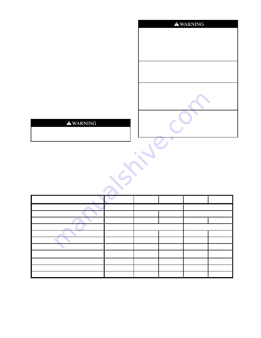
Table 1: Physical Data

VT Physical Data

MODEL

036

042

048

060

072

Fan Wheel (Dia. X Width), in.

9 X 7

Fan Motor & HP

ECM - 1/2

ECM - 1/2

ECM - 1

No. Refrigerant Circuits

2

2

2

2

2

Compressors

2 - Rotary

No. Coaxial Heat Exchangers

2

2

2

2

2

R - 22 Charge (Sys A / Sys B), oz

40 / 40

57 / 59

62 / 62

54 / 54

58 / 58

Water Connection Size (fpt swivel)

1"

1"

1"

1"

1"

Air Coil Length x Height, in.

20 X 24

24 X 24

24 X 32

24 X 36

24 X 36

Filter - 1" ElectroStatic (Std.)

24 x 24

27 x 31

27 x 31

27 x 35

27 x 35

Weight - Operating (lbs.)

225

275

305

385

450

Weight - Packaged (lbs.)

235

285

315

395

460

Rev.: 8/07/04D

All units have txv expansion devices, 20 ga sheet metal,
and 7/8" & 1-1/8" electrical knockouts.
All units have dual 1" Swivel water connections (4 total)
HWG utilizes 1/2" fpt water connections and is available only on circuit A.
All units have 3/4" fpt condensate drain connections.

Revision

Date

Data from Tom North 9/00

10/30/00

Changed filter rack and filter data checked with Enertech

11/13/00

Changes for new comp in 036, 060, and 072 and Electrost Filter & Rack Std 3/30/01

2 - Scroll

11 X 10

11 X 10

ECM - 1

2 - Scroll

Removed Air Coil Data

8/07/04

GENERAL INFORMATION

Summary of Contents for Ultra Classic VT 036

Page 1: ...Information 22 Troubleshooting Analysis 23 Major Replacement Components 24 Unit Start Up Procedure 26 Operating Limits 26 Pressure Drop Table 28 Operating Pressures 28 Warranty 31 Preventive Maintena...

Page 2: ...ts have been received Inspect the carton or crating of each unit and inspect each unit for damage Assure the carrier makes proper notation of any shortages or damage on all copies of the freight bill...

Page 3: ...unit start up read all manuals and become familiar with the unit and its operation Thoroughly check the system before operation Prepare units for installation as follows 1 Compare the electrical data...

Page 4: ...Page Ultra Classic VT Series Physical Dimensions INSTALLATION...

Page 5: ...e connector is recommended for both discharge and return air duct connections on metal duct systems Uninsulated duct should be insulated with a minimum of one inch duct insulation Application of the u...

Page 6: ...essure temperature taps for serviceability run When some sagging in the condensate line may be anticipated as in a long line of plastic pipe or when double trapping may occur Also vent when large unit...

Page 7: ...re operation Flush the loop with a high volume of water at a high velocity 2 fps in all piping both directions The steps below must be followed for proper flushing Fill loop with water from a garden h...

Page 8: ...s however your local territory manager should be consulted for the antifreeze best suited to your area Freeze protection should be maintained to 15 F below the lowest expected entering loop temperatur...

Page 9: ...cal building and zoning department to assure compliance in your area OPEN LOOP WELL WATER SYSTEMS Water Control Valve Note the placement of the water control valve Always maintain water pressure in th...

Page 10: ...e examined for feasibility before installation City water should not be used as a source in areas where water temperatures fall below 45 F ClimateMaster should be consulted when sizing earth loops for...

Page 11: ...hown in Figure 15 is the most efficient system providing the maximum storage and temperate source water to the desuperheater Using a concentric hot water tank connection fitting eliminates the need to...

Page 12: ...eat available from the refrigeration system and con serve the most energy On tanks with both upper and lower elements and thermostats the lower element should be turned down to 100 F or lowest setting...

Page 13: ...own on the unit serial plate Line and low voltage wiring must be done in accordance with local codes or the National Electric Code whichever is applicable Unit Power Connection Line voltage connection...

Page 14: ...used 2 stage heat 2 stage cool or 3 stage heat 2 stage cool Note Power must be off to the unit for at least three seconds before the ECM motor will recognize a speed change The motor will recognize a...

Page 15: ...17B0019N01 DIP Switch Version II Version II 17B0019N01 Version II 17B0019N01 DIP Switch DIP Switch ON OFF DIP Switch Version II 17B0019N01 DIP Switch 17B0019N01 SW9 Table 6 ECM Board Tap Settings Y G...

Page 16: ...wg hp Setting Stg 2 Stg 1 Fan Stg 2 Stg 1 Fan Setting Mode 4 1290 710 650 1010 550 650 4 1290 036 0 5 1 2 3 1200 660 600 940 520 600 3 1200 2 1110 610 560 870 480 560 2 1110 1 1020 560 510 1 1020 4 1...

Page 17: ...valve takes approximately 60 seconds to open very little water will flow before 45 seconds and it activates the compressor only after the valve is completely opened by closing its end switch Only rel...

Page 18: ...Page 18 Ultra Classic VT Series Electrical Schematic...

Page 19: ...ault For Diagnostic ease at the thermostat the alarm relay will also cycle during test mode The Alarm relay will cycle on and off similar to the status LED to indicate a code representing the last fau...

Page 20: ...Switch input is bypassed for the initial 60 seconds of a compressor run cycle Low Pressure Lockout Code 3 thermistor temperature must be below the selected freeze protection limit setting for 30 cont...

Page 21: ...ng Stage 1 mode Y becomes active The first time after power up that there is a call for compressor the compressor will follow a 5 to 80 second random start delay There will also be a 5 min compressor...

Page 22: ...d at the board connector The thermistor resistance should be measured with the connector removed so that only the impedance of the thermistor is measured If desired this reading can be compared to the...

Page 23: ...ower before servicing can cause severe personal injury or death TROUBLE ANALYSIS If operational difficulties are encountered be sure to perform the preliminary checks before referring to the Troublesh...

Page 24: ...cooling Check fan motor operation and airflow restrictions Too high of external static Check static vs blower table X Air Temperature out of range Too much cold vent air Bring entering air temp within...

Page 25: ...ng in water heat exchanger Perform Scaling check and clean if necessary X X Inlet Water too Hot or Cold Check load loop sizing loop backfill ground moisture High Head Pressure X Reduced or no Air flow...

Page 26: ...ing Conditions GT X Units Units start and operate in an ambient of 45 F with entering air at 45 F entering water at 32 F and both air and water at the stated flow rates of ISO ASHRAE ARI 13256 1 for i...

Page 27: ...it pressure drop across the heat exchanger versus the data in Table 12 Heat of rejection can be calculated and compared to specification catalog f Check air temperature drop across the coil when compr...

Page 28: ...Page 28 Ultra Classic VT Series Table 14 Unit operating pressures and temperatures Table 12 Water Temperature Change Through Heat Exchanger Table 13 Water Pressure Drop Table...

Page 29: ...Ultra Classic VT Series Page 29 Notes...

Page 30: ...Page 30 Ultra Classic VT Series...

Page 31: ...or use of CM s products or 13 Electricity or fuel costs or any increases or unrealized savings in same for any reason whatsoever CM is not responsible for 1 The costs of any fluids refrigerant or sys...

Page 32: ...t can erode the heat exchanger wall and ultimately produce leaks Filters Filters must be clean to obtain maximum performance They should be inspected every month under normal operating conditions and...

Reviews: