


18
C l i m a t e M a s t e r Wa t e r- S o u rc e H e a t P u m p s
C L I M A T E M A S T E R W A T E R - S O U R C E H E A T P U M P S
Tr a n q u i l i t y
®
3 0 ( T T ) S e r i e s
R e v. : 0 7 / 1 8 / 1 3
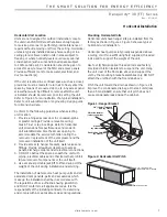
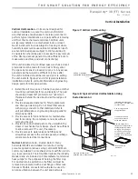
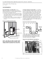
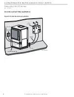
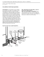
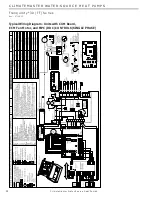
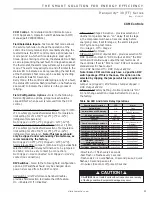
Figure 14: Typical Open Loop/Well Application
3UHVVXUH
7DQN
6KXW2II
9DOYH
%RLOHU
'UDLQV
)ORZ
5HJXODWRU
:DWHU,Q
:DWHU2XW
:DWHU
&RQWURO
9DOYH
2SWLRQDO
)LOWHU
373OXJV
Ground-Water Heat Pump Applications
Flow Regulation
- Flow regulation can be accomplished
by two methods. One method of fl ow regulation involves
simply adjusting the ball valve or water control valve on
the discharge line. Measure the pressure drop through the
unit heat exchanger, and determine fl ow rate from Tables
8a through 8e. Since the pressure is constantly varying, two
pressure gauges may be needed. Adjust the valve until the
desired fl ow of 1.5 to 2 gpm per ton [2.0 to 2.6 l/m per kW]
is achieved. A second method of fl ow control requires a fl ow
control device mounted on the outlet of the water control
valve. The device is typically a brass fi tting with an orifi ce of
rubber or plastic material that is designed to allow a specifi ed
fl ow rate. On occasion, fl ow control devices may produce
velocity noise that can be reduced by applying some back
pressure from the ball valve located on the discharge line.
Slightly closing the valve will spread the pressure drop over
both devices, lessening the velocity noise.
Note: When EWT is below 50°F [10°C], 2 gpm per
ton (2.6 l/m per kW) is required.
Water Coil Low Temperature Limit Setting
- For all
open loop systems the 30°F [-1.1°C] FP1 setting (factory
setting-water) should be used to avoid freeze damage to
the unit. See “Low Water Temperature Cutout Selection” in
this manual for details on the low limit setting.


