ClimateMaster Tranquility 97B0072N01 Installation, Operation & Maintenance Instructions Manual Download Page 23

23

R e s i d e n t i a l   D i g i t a l   H & V   -   Tr a n q u i l i t y

®

  2 2   D i g i t a l   ( T Z )   S e r i e s   -   6 0 H z   H F C - 4 1 0 A

C r e a t e d :   2 6   O c t . ,   2 0 1 1 B

c l i m a t e m a s t e r. c o m
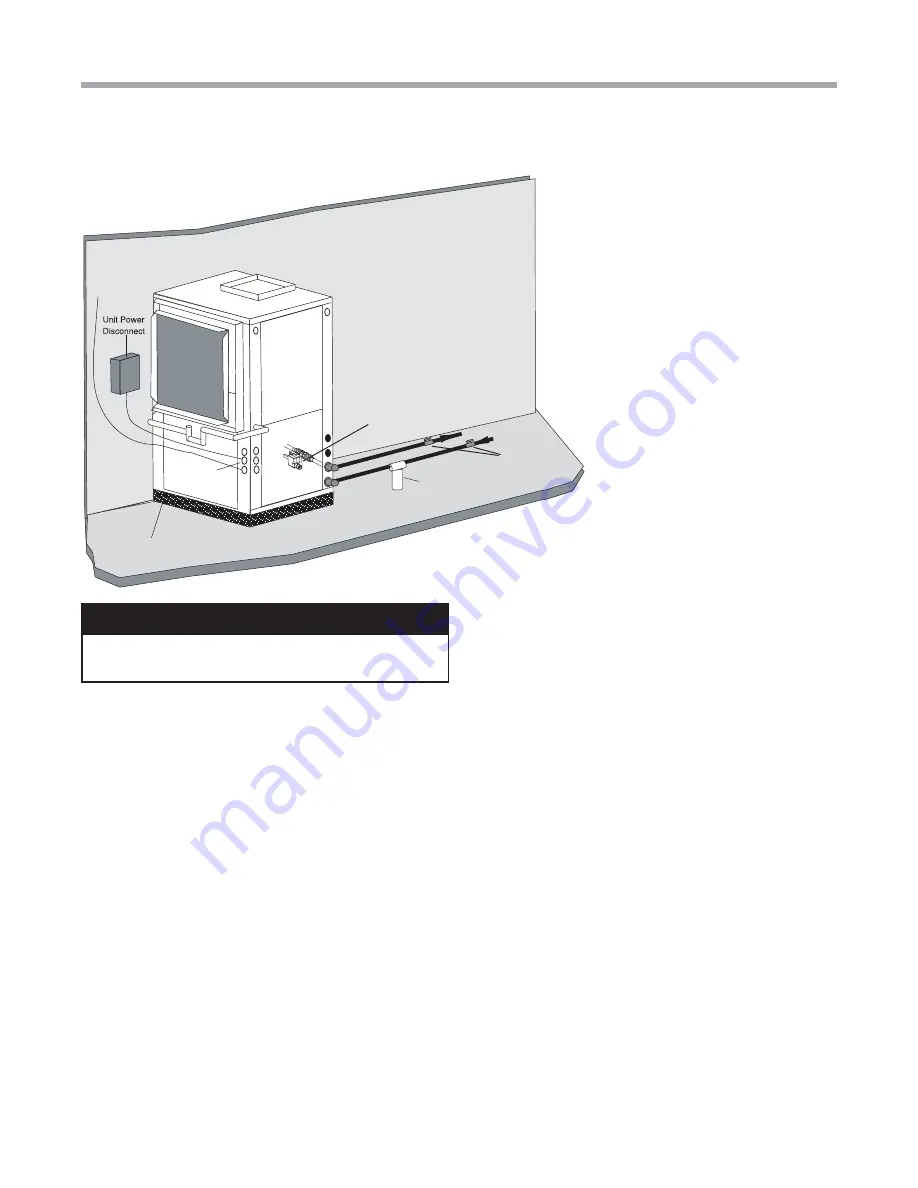
High and 
Low Voltage 
Knockouts

Vibration Isolation Pad

To Thermostat

Internal Motorized 

Modulating Valve

Water In

Water Out

Optional

Filter

Shut Off

Ball Valves

 for Isolation

Ground-Water Heat Pump Applications

With industry-leading ‘plug and play options, for a ground 
water (open) loop, a TZ unit with a motorized modulating 
valve for the water circuit would be used.

Open Loop - Ground Water Systems

Typical open loop piping is shown in Figure 17. Shut off valves 
should be included for ease of servicing. Boiler drains or other 
valves should be “tee’d” into the lines to allow acid 

fl

 ushing 

of the heat exchanger. Shut off valves should be positioned 
to allow 

fl

 ow through the coax via the boiler drains without 

allowing 

fl

 ow into the piping system.  Pressure plugs built 

into unit should be used to measure pressure drop. Water 
temperature can be viewed on the communicating thermostat. 
Piping materials should be limited to copper or PVC SCH80. 
Note: Due to the pressure and temperature extremes, PVC 
SCH40 is not recommended.

Water quantity should be plentiful and of good quality. 
Consult table 3 for water quality requirements. The unit 
can be ordered with either a copper or cupro-nickel water 
heat exchanger. Consult table 3 to determine which heat 
exchanger to use. Copper is recommended for closed loop 
systems and open loop ground water systems that are not 
high in mineral content or corrosiveness. In installations 
anticipating heavy scale formation or in brackish water, a 
cupro-nickel heat exchanger is recommended. In ground 
water situations where scaling could be heavy or where 

Figure 17: Typical Open Loop/Well Application


CAUTION! 

CAUTION!

 Refrigerant pressure activated water regulating 

valves should never be used with this equipment.

biological growth such as iron bacteria will be present, an 
open loop system is not recommended. Heat exchanger 
coils may over time lose heat exchange capabilities due to 
build up of mineral deposits. Heat exchangers must only 
be serviced by a quali

fi

 ed technician, as acid and special 

pumping equipment is required. Desuperheater coils can 
likewise become scaled and possibly plugged. In areas with 
extremely hard water, the owner should be informed that the 
heat exchanger may require occasional acid 

fl

 ushing.  In some 

cases, the desuperheater option should not be recommended 
due to hard water conditions and additional maintenance 
required.

Water Quality Standards

Table 3 should be consulted for water quality requirements. 
Scaling potential should be assessed using the pH/
Calcium hardness method. If the pH <7.5 and the Calcium 
hardness is less than 100 ppm, scaling potential is low. If 
this method yields numbers out of range of those listed, the 
Ryznar Stability and Langelier Saturation indecies should be 
calculated. Use the appropriate scaling surface temperature 
for the application, 150°F [66°C] for direct use (well water/
open loop) and DHW (desuperheater); 90°F [32°F] for 
indirect use. A monitoring plan should be implemented in 
these probable scaling situations. Other water quality issues 
such as iron fouling, corrosion prevention and erosion and 
clogging should be referenced in Table 3.

Pressure Tank and Pump

Use a closed, bladder-type pressure tank to minimize 
mineral formation due to air exposure. The pressure tank 
should be sized to provide at least one minute continuous 
run time of the pump using its drawdown capacity rating to 
prevent pump short cycling. Discharge water from the unit 
is not contaminated in any manner and can be disposed 
of in various ways, depending on local building codes (e.g. 

Summary of Contents for Tranquility 97B0072N01

Page 1: ...Cutout Selection 20 Internal Flow Controller Pump Curves 21 Pump Replacement Procedure 22 Ground Water Heat Pump Applications 23 Water Quality Standards 25 Hot Water Generator 26 28 Electrical Line Vo...

Page 2: ...This page was intentionally left blank...

Page 3: ...ls on unit access panels must be observed WARNING Indicates a potentially hazardous situation which if not avoided could result in death or serious injury CAUTION Indicates a potentially hazardous sit...

Page 4: ...amiliar with the unit and its operation Thoroughly check the system before operation Prepare units for installation as follows 1 Compare the electrical data on the unit nameplate with ordering and shi...

Page 5: ...to freely enter the space by means of a louvered door etc Any access panel screws that would be difficult to remove after the unit is installed should be removed prior to setting the unit Refer to Fig...

Page 6: ...ainst higher external static pressure than other units connected to the same condensate main since this may cause poor drainage for all units on the line WHEN A VENT IS INSTALLED IN THE DRAIN LINE IT...

Page 7: ...cian during the removal or replacement of the compressor and the removal or installation of the unit itself 2 Provide access to hanger brackets water valves and fittings Provide screwdriver clearance...

Page 8: ...Installation with Internal Flow Controller Air Coil To obtain maximum performance the air coil should be cleaned before start up A 10 solution of dishwasher detergent and water is recommended for both...

Page 9: ...he screws as shown in Figure 8 to free top panel and discharge panel 2 Lift out the access panel and set aside Lift and rotate the discharge panel to the other position as shown being careful with the...

Page 10: ...abinet Install condensate trap at each unit with the top of the trap positioned below the unit condensate drain connection as shown in Figure 10 Design the depth of the trap water seal based upon the...

Page 11: ...low control The three possible alternatives are 1 Internal Flow Controller For Closed Loop Applications Primarily for use on closed loop applications with a single unit With this factory installed sta...

Page 12: ...m to ALL applicable codes It is the responsibility of the installing contractor to determine and comply with ALL applicable codes and regulations Heat Pump Applications High and Low Voltage Knockouts...

Page 13: ...ground source system is shown in Figure 12a All earth loop piping materials should be limited to polyethylene fusion only for in ground sections of the loop Galvanized or steel fittings should not be...

Page 14: ...kW pump is needed to achieve adequate flow velocity in the loop to purge air and dirt particles from the loop itself Antifreeze solution is used in most areas to prevent freezing All air and debris mu...

Page 15: ...p purge air pockets by simply shutting off the return valve going into the flush cart reservoir This process dead heads the pump to 50 psi 345 kPa To dead head the pump until maximum pumping pressure...

Page 16: ...allow loop pressure to compress the expansion tank bladder thus charging the expansion tank with liquid After pressurizing close the flush cart supply valve to isolate the flush cart Move the Flow Co...

Page 17: ...roperly Antifreeze Selection General In areas where minimum entering loop temperatures drop below 40 F 4 4 C or where piping will be routed through areas subject to freezing antifreeze is needed Alcoh...

Page 18: ...of toxic substances such as methanol benzene or gasoline as a denaturant Many of these denaturants are difficult to identify by the casual user and many are not compatible with polyethylene pipe Only...

Page 19: ...of exposed piping and Flow Controller to ambient conditions 4 Isolate unit and prepare to flush only through loop Start flush cart and gradually introduce the required amount of liquid to the flush c...

Page 20: ...ate as the fluid temperature changes Typical earth loop pressures range from approximately 15 50 psi 103 345 kPa At the start up of a system the earth loops should have a static holding pressure of ap...

Page 21: ...es 60Hz HFC 410A Created 26 O c t 2 0 1 1 B climatemaster com Chart 2 Internal Variable Speed Flow Controller Maximum Performance Internal Flow Controller Pump Curves 0 10 20 30 40 50 60 0 5 10 15 20...

Page 22: ...gallons 7 8 liters If performed more than twice on any earth loop the antifreeze concentration should be checked with a hydrometer and antifreeze added as needed 1 Close valves as shown in Figure 16...

Page 23: ...l Application CAUTION CAUTION Refrigerant pressure activated water regulating valves should never be used with this equipment biological growth such as iron bacteria will be present an open loop syste...

Page 24: ...ations should be considered for the inherent energy savings and smaller pressure tank requirements Internal Motorized Modulating Valve TZ series units are available with an internal motorized modulati...

Page 25: ...per alloy bronze or brass cast components are OK to 0 5 ppm Ammonia ion as hydroxide chloride nitrate and sulfate compounds All 0 5 ppm Maximum Maximum Allowable at maximum water temperature Chloride...

Page 26: ...l The temperature set point of the HWG is field selectable to 125 F or 150 F The 150 F set point allows more heat storage from the HWG For example consider the amount of heat that can be generated by...

Page 27: ...E HWG PIPING IS CONNECTED FILLED WITH WATER AND PURGED OR PUMP DAMAGE WILL OCCUR When the control is powered and the HWG pump output is active for water temperature sampling or HWG operation the DXM2...

Page 28: ...hat the HWG valves valves 2 and 3 are open Open the cold water supply valve 1 to fill the tank through the HWG piping This will purge air from the HWG piping 2 Open a hot water faucet to vent air from...

Page 29: ...0 6 32 3 30 030 14 7 73 0 1 0 4 1 7 3 9 20 7 24 3 39 0 35 036 18 0 83 0 1 0 4 1 7 3 9 23 9 28 4 46 3 45 042 21 8 96 0 1 0 4 1 7 5 2 29 1 34 5 56 3 50 048 25 0 104 0 1 0 4 1 7 5 2 32 2 38 5 63 5 60 060...

Page 30: ...only copper conductors for field installed electrical wiring Unit terminals are not designed to accept other types of conductors Unit Power Supply see electrical table for minimum circuit amps and ma...

Page 31: ...be wired directly to the DXM2 board Figure 22 shows wiring for TZ units See Electrical Thermostat for specific terminal connections Low Water Temperature Cutout Selection The DXM2 control allows the...

Page 32: ...ow voltage terminal strip on the DXM2 control board Practically any heat pump thermostat will work with these units provided it has the correct number of heating and cooling stages Thermostat Connecti...

Page 33: ...o Y1 Y2 or W Dehumidification Mode Settings The dehumidification mode settings provide field selection of humidity control When operating in the normal mode the cooling airflow settings are determined...

Page 34: ...0 575 950 650 450 950 Maximum 1100 750 1000 700 1100 1100 1100 1100 Minimum 750 525 750 525 750 525 375 750 036 0 6 1 2 Default 1125 750 975 650 1125 750 525 1125 Maximum 1250 950 1200 800 1250 1250 1...

Page 35: ...Stage 2 demand Also if set for stage 2 the alarm relay will NOT cycle during test mode On Stage 1 Off Stage 2 1 3 Thermostat type heat pump or heat cool DIP 1 3 provides selection of thermostat type...

Page 36: ...inspection and remedy of faulting condition Equipment damage may occur DIP 2 1 DIP 2 2 DIP 2 3 ACC1 Relay Option On On On Cycle with fan Off On On Digital NSB On Off On Water Valve slow opening On On...

Page 37: ...relay will be energized On all subsequent compressor calls the random start delay is omitted 240Vac Com N O Fan Enable Test P5 B Gnd P4 A 24V 240Vac Fan Speed N O N C 12V OUT Gnd P8 IN NC P12 Pust te...

Page 38: ...W is 20mA Triacs can be used if leakage current is less than above Thermostats with anticipators can be used if anticipation current is less than that specified above Thermostat Signals Y1 Y2 W1 O and...

Page 39: ...r continuous operating conditions Minimum maximum limits are start up conditions to bring the building space up to occupancy temperatures Units are not designed to operate under these conditions on a...

Page 40: ...must be potable quality initially and clean of dirt piping slag and strong chemical cleaning agents Some antifreeze solutions may require distilled water Internal Flow Controller Verify that it is pu...

Page 41: ...emperature is outside of the operating range check refrigerant pressures and compare to Table 13 Verify correct water flow by comparing unit pressure drop across the heat exchanger versus the data in...

Page 42: ...4 7 7 4 1 1 1 7 2 0 3 5 5 6 0 9 1 3 1 7 3 0 4 9 0 8 1 2 1 5 2 8 4 7 060 6 0 7 5 9 0 12 0 15 0 4 0 5 4 6 8 10 6 16 2 2 6 3 8 4 9 7 9 12 8 2 4 3 3 4 4 7 0 11 1 2 4 3 3 4 3 6 7 10 1 Based on 15 methanol...

Page 43: ...2 17 22 88 98 96 106 105 115 353 373 361 381 370 390 6 11 8 13 9 14 12 17 12 17 12 17 13 2 15 2 9 0 11 0 4 8 6 8 24 29 25 30 26 31 70 1 5 2 25 3 128 138 124 134 119 129 328 348 300 320 273 293 8 13 9...

Page 44: ...7 8 7 10 7 20 25 20 25 20 25 94 104 100 110 105 115 343 363 350 270 356 376 9 14 10 15 10 15 12 18 11 16 10 15 11 3 13 3 8 2 10 2 5 0 8 0 25 30 26 31 26 31 70 1 5 2 25 3 124 134 124 134 123 133 300 32...

Page 45: ...1 17 2 1 60 15 0 29 6 19 7 2 6 3 0 1 9 4 4 750 28 1 1 78 4 6 14 7 22 0 34 6 3 2 4 5 3 4 7 9 600 24 2 16 1 1 40 17 3 29 0 12 9 2 3 4 5 3 4 7 9 600 28 9 1 88 4 5 10 0 22 4 44 5 3 2 4 5 3 4 7 9 750 24 8...

Page 46: ...4 2 27 0 45 5 4 1 3 8 1 0 2 2 900 30 7 19 9 2 03 15 1 37 6 19 8 3 5 3 8 1 0 2 2 900 36 0 2 36 4 5 14 7 28 0 37 1 4 3 5 6 2 0 4 5 720 30 9 18 7 1 78 17 4 37 0 13 2 3 1 5 6 2 0 4 5 720 37 0 2 51 4 3 10...

Page 47: ...1 42 3 5 2 4 5 1 5 3 5 1150 36 4 24 2 2 41 15 1 44 6 19 8 4 4 4 5 1 5 3 5 1150 42 7 2 81 4 5 14 7 33 2 34 4 5 3 6 8 2 0 4 6 920 36 6 22 7 2 12 17 2 43 9 12 9 3 8 6 8 2 0 4 6 920 43 9 2 98 4 3 9 9 33...

Page 48: ...43 5 5 2 5 3 1 5 3 4 1300 44 1 33 1 2 81 15 7 53 7 20 5 3 7 5 3 1 5 3 4 1300 50 1 3 33 4 4 14 8 38 8 35 7 5 3 7 9 3 1 7 2 1050 44 4 31 0 2 46 18 0 52 8 13 4 3 2 7 9 3 1 7 2 1050 51 5 3 53 4 3 10 0 39...

Page 49: ...9 4 4 8 6 0 1 3 3 1 1200 53 7 3 46 4 6 13 9 41 8 41 4 4 9 6 0 1 3 3 1 1500 49 1 33 9 3 21 15 3 60 0 20 0 4 9 6 0 1 3 3 1 1500 54 6 3 32 4 8 14 4 43 2 33 7 5 1 9 0 3 0 6 9 1200 49 4 31 8 2 78 17 7 58 8...

Page 50: ...16 1 74 6 19 9 5 0 7 5 3 3 7 7 1900 69 6 4 61 4 4 14 4 53 9 33 9 6 5 11 3 6 3 14 5 1525 62 0 42 2 3 36 18 4 73 4 13 0 4 4 11 3 6 3 14 5 1525 71 3 4 88 4 3 9 7 54 7 43 3 6 5 11 3 6 3 14 5 1900 63 5 45...

Page 51: ...e EWT LWT and GPM U S Gallons per Minute TD HE GPM x 500 TD 22 500 4 5 x 500 TD 10 F LWT EWT TD LWT 50 10 40 F In this example as long as the EWT does not fall below 50 F the system will operate as de...

Page 52: ...0 12 65 4 93 12602 3 90 3 00 9826 1 87 2 21 8445 0 57 1 34 6574 15 0 0 0 14 27 5 28 13496 4 39 3 22 10546 2 11 2 36 9018 0 65 1 43 7015 16 0 0 0 15 97 5 64 14416 4 92 3 43 11234 2 37 2 52 9629 0 72 1...

Page 53: ...6 0 58 1 24 3445 14 0 0 0 14 58 4 93 7136 4 49 3 00 5564 2 16 2 21 4782 0 66 1 34 3723 15 0 0 0 16 45 5 28 7643 5 07 3 22 5972 2 44 2 36 5107 0 74 1 43 3973 16 0 0 0 18 41 5 64 8164 5 67 3 43 6362 2 7...

Page 54: ...0 12 98 4 93 11366 4 00 3 00 8862 1 92 2 21 7616 0 59 1 34 5929 15 0 0 0 14 64 5 28 12173 4 51 3 22 9512 2 17 2 36 8133 0 66 1 43 6327 16 0 0 0 16 39 5 64 13003 5 05 3 43 10132 2 43 2 52 8685 0 74 1 5...

Page 55: ...099 0 28 1 15 13 922 13 7 09 4 58 29 128 2 18 2 79 22 408 1 05 2 05 19 607 0 32 1 24 15 082 14 8 07 4 93 31 369 2 49 3 00 24 132 1 20 2 21 2 115 0 36 1 34 16 242 15 9 11 5 28 33 609 2 81 3 22 25 855...

Page 56: ...rs Filters must be clean to obtain maximum performance Filters should be inspected every month under normal operating conditions and be replaced when necessary Units should never be operated without a...

Page 57: ...hipped or dry contacts for use with DDC controls by clipping the JW1 jumper Electric heat outputs are 24VDC ground sinking and require a voltmeter set for DC to verify operation The terminal marked 24...

Page 58: ...ns Start Did Unit Attempt to Start Did Unit Lockout at Start up Unit Short Cycles Only Fan Runs Only Compressor Runs Did unit lockout after a period of operation Does unit operate in cooling Unit is O...

Page 59: ...g 30 F vs 10 F Normal airside applications will require 30 F only X X Bad thermistor Check temp and impedance correlation per chart Condensate Fault Code 6 X X Blocked drain Check for blockage and cle...

Page 60: ...X X Unit locked out Check for lockout codes reset power X X Compressor overload Check compressor overload replace if necessary X X Thermostat wiring Check thermostat wiring at DXM2 put in Test Mode a...

Page 61: ...k superheat and subcooling per chart replace Low Suction Pressure X Reduced water flow Check pump operation or water valve operation setting in heating Plugged strainer or filter clean or replace Chec...

Page 62: ...ILTER DRIER FLASH GAS LINE F LT1 SENSOR F EXPANSION VALVE FILTER DRIER LT2 FLASH GAS LINE F OTHER SIDE OF FILTR DR F LT1 CLG LIQ LINE F Refrigerant Type HFC 410A Heat of Extraction Absorption or Heat...

Page 63: ...63 Residential Digital H V Tranquility 22 Digital TZ Series 60Hz HFC 410A Created 26 O c t 2 0 1 1 B climatemaster com...

Page 64: ...herein Please contact ClimateMaster s Customer Service Department at 1 405 745 6000 for specific information on the current design and specifications Statements and other information contained herein...

Reviews: