34
C l i m a t e M a s t e r W a t e r- S o u r c e H e a t P u m p s
C L I M A T E M A S T E R W A T E R - S O U R C E H E A T P U M P S
Tr a n q u i l i t y
®
2 2 ( T Y ) S e r i e s
R e v. : 1 2 / 1 7 / 1 4
P1
Alarm
Relay
Comp
Relay
O
Y1
Y2
W
G
C
R
AL1
24Vdc
EH1
EH2
P6
R
C
Off On
JW3
A
OVR
ESD
C
R
NSB
AL2
JW1
Acc1
Relay
Acc2
Relay
H
COM1
NC1
NO1
COM2
NC2
NO2
P3
CO
RV
RV
LT1
LT1
LT2
LT2
LP
LP
HP
HP
P7
Status
Fault
R
R
CC
CCG
CO
S1
S2
1
12
1
4
e
s
U
yr
ot
c
a
F
(240Vac)
Com
N.O.
Fan Enable
Micro
U1
Off On
P2
COH
COM
AO2
P11
Gnd
T1
P10
T2 T2 T3
T3 T4 T4
T5
P9
T5 T6 T6
A0-1 A0-2
Off On
S3
RV
Relay
CCH
Relay
Test
P5
B-
Gnd
P4
A+ 24V
(240Vac)
Fan Speed
N.O.
N.C.
12V
OUT
Gnd
P8
IN
NC
P12
1 2 3 4
1 2 3 4 5 6 7 8
1 2 3 4 5 6 7 8
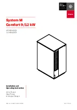
Service tool
connection
Communicating
stat connection
Conventional
stat connection
Cabinet
temperature
sensor
(with variable
speed pump)
24V to compressor
second-stage solenoid
for Y2/full
load capacity
Use 4 mounting screws
#6 sheet metal screw
1” long
Configure
modulating valve
or variable
speed pump
V
a
riable
speed pump
Entering
water temp
Leaving
water temp
Leaving
air temp
Electric heat
connection
Factory low
voltage molex
connection for
unit harness
Entering Hot water
T
e
mperature
Compressor Discharge
temperature
ECM Motor
Connection
Test Button
to Speed up
Time Delays
Communications
and HWG
Settings
Water Coil
Low Temp
Limit Setting.
JWT-LT1 jumper
should be clipped
for low temp
(antifreeze)
operation
Accessory
relays refer
to DXM2 AOM
for configuration
DXM2 Layout and Connections