ClimateMaster TMW036 Installation Operation & Maintenance Download Page 22

C L I M A T E M A S T E R   W A T E R - S O U R C E   H E A T   P U M P S

Tranquility

®

 Water-to-Water (TMW) Series

R e v. :   0 4 / 1 5 / 1 6

22

C l i m a t e M a s t e r   Wa t e r - S o u rc e   H e a t   P u m p s

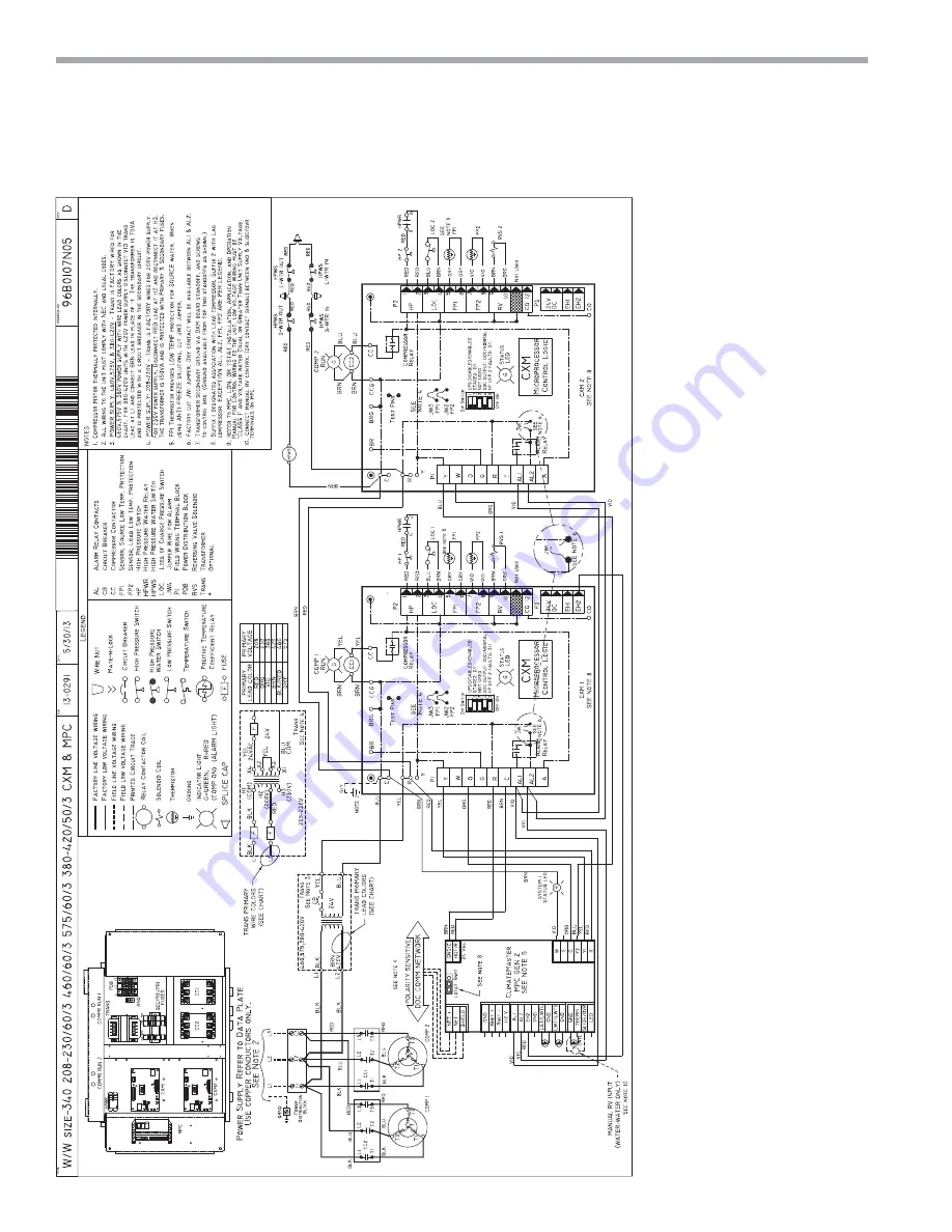
Typical Wiring Diagram Three Phase - TMW 340 Units with CXM & MPC Controller

Summary of Contents for TMW036

Page 1: ...tions 11 Ground Water Heat Pump Applications 12 Ground Loop Heat Pump Applications 14 Electrical Line Voltage 16 Electrical Accessories 17 Electrical Line Voltage 18 Electrical Low Voltage 19 TMW Seri...

Page 2: ...CL IM A TEM ASTER WATER SOURCE HEAT PUMPS Tranquility Water to Water TMW Series R ev 04 15 16 2 ClimateMaster Water Source Heat Pumps This Page Intentionally Left Blank...

Page 3: ...PER LOAD WATER COILOPTIONS N CUPRO NICKEL S STANDARD 0 NONE RESERVED FOR FUTURE OPTIONS 0 NONE 060 F G H N U 120 F G H N U 170 F H N U 340 F H N U 2 COMMERCIALEXTENDED RANGE w ULTRAQUIET 2 HWG COILONL...

Page 4: ...ally hazardous situation which if not avoided could result in death or serious injury CAUTION Indicates a potentially hazardous situation or an unsafe practice which if not avoided could result in min...

Page 5: ...installation site chosen should include adequate service clearance around the unit Before unit start up read all manuals and become familiar with the unit and its operation Thoroughly check the syste...

Page 6: ...1 1 2 2 Hot Water Generator FPT in N A Weight Operating lbs kg 348 158 360 163 726 329 725 329 1330 604 Weight Packaged lbs kg 373 169 385 175 770 349 765 347 1340 608 Water Volume Source Gallons Lite...

Page 7: ...ht D Source Outdoor Water In E Source Outdoor Water Out F Load Indoor Water In G Load Indoor Water Out H HWG Water In J HWG Water Out K Low Voltage L External Pump M Power Supply 036 060 in 30 6 25 4...

Page 8: ...O 4 5 114 2 IPT Water Connections 15 0 381 5 4 138 21 0 533 Fault Run Lights 64 5 1638 Left Side View Front View Top View Load Source Side Refrig Circuit Access Panel Front Compressor Access Panel Ele...

Page 9: ...sealant from reaching the flared surfaces of the joint TMW Unit Location These units are not designed for outdoor installation Locate the unit in an INDOOR area that allows enough space for service p...

Page 10: ...able Similar hoses can be obtained from alternate suppliers Supply and return hoses are fitted with swivel joint fittings at one end to prevent kinking during installation Refer to Figure 1 for an ill...

Page 11: ...ecommends 2 5 gpm Air Pad or Extruded polystyrene insulation board Unit Power Disconnect Pressure Tank Flow Regulator Water Control Valve P T Plugs Water Out Shut Off Valve Boiler Drains Water In Opti...

Page 12: ...e compounds All 0 5 ppm Maximum Maximum Allowable at maximum water temperature Chloride Levels 10 C 24 C 38 C Copper Cupronickel 20ppm NR NR 150 ppm NR NR 304 SS 400 ppm 250 ppm 150 ppm 316 SS 1000 pp...

Page 13: ...installed with a factory or field supplied manual or electric shut off valve DAMAGE WILL OCCUR if shut off valve is closed during unit operation A high pressure switch must be installed on the heat pu...

Page 14: ...ntifreeze Percentages by Volume Antifreeze In areas where minimum entering loop temperatures drop below 40 F 5 C or where piping will be routed through areas subject to freezing anti freeze is needed...

Page 15: ...All 208 230 Volt units are factory wired for 208 Volt The transformers may be switched to 230V operation as illustrated on the wiring diagram by switching the Red 208V and the Orange 230V at the cont...

Page 16: ...Min Circuit Amps Max Fuse HACR Qty RLA LRA TMW036 G 208 230 60 1 187 254 1 16 7 79 16 7 20 8 35 E 265 60 1 239 292 1 13 5 72 13 5 16 8 30 H 208 230 60 3 187 254 1 10 4 73 10 4 13 1 20 F 460 60 3 414 5...

Page 17: ...B0004N01 DPDT VR3 Coil 6 8 Refrigerant HP Switch Circuit 1 VR3 NO RED RED Coil Valve Relay 3 Water High Pressure Switch NC Coil VR2 2 4 Refrigerant HP Switch Circuit 2 VR3 NO RED RED 2 4 Refrigerant H...

Page 18: ...e of the compressor access panel to ensure proper electrical hookup All final electrical connections must be made with a length of flexible conduit to minimize vibration and sound transmission to the...

Page 19: ...shown in Figure 7 to change the setting to 10 F a more suitable temperature when using antifreezes It should be noted that the extended range option should be specified to operate the TMW Series at en...

Page 20: ...575 60 3 96B0224N02 208 230 60 1 TMW060 ONLY TMW120 96B0225N02 208 230 60 1 CXM MPC LON 96B0225N03 208 230 60 3 460 60 3 575 60 3 MPC LON 96B0225N05 208 230 60 1 DXM MPC LON 96B0225N06 208 230 60 3 4...

Page 21: ...THE SMART SOLUTION FOR ENERGY EFFI C I E NC Y Tranquility Water to Water TMW Series R ev 0 4 1 5 1 6 21 climatemaster com Typical Wiring Diagram Three Phase TMW 170 Units with CXM Controller...

Page 22: ...M A TEM ASTER WATER SOURCE HEAT PUMPS Tranquility Water to Water TMW Series R ev 04 15 16 22 ClimateMaster Water Source Heat Pumps Typical Wiring Diagram Three Phase TMW 340 Units with CXM MPC Control...

Page 23: ...THE SMART SOLUTION FOR ENERGY EFFI C I E NC Y Tranquility Water to Water TMW Series R ev 0 4 1 5 1 6 23 climatemaster com Typical Wiring Diagram Three Phase TMW 340 Units with CXM Controller...

Page 24: ...CL IM A TEM ASTER WATER SOURCE HEAT PUMPS Tranquility Water to Water TMW Series R ev 04 15 16 24 ClimateMaster Water Source Heat Pumps Typical Wiring Diagram Three Phase TMW 340 Units with DXM...

Page 25: ...THE SMART SOLUTION FOR ENERGY EFFI C I E NC Y Tranquility Water to Water TMW Series R ev 0 4 1 5 1 6 25 climatemaster com Typical Wiring Diagram Three Phase TMW 170 Units with DXM Controller...

Page 26: ...CL IM A TEM ASTER WATER SOURCE HEAT PUMPS Tranquility Water to Water TMW Series R ev 04 15 16 26 ClimateMaster Water Source Heat Pumps Typical Wiring Diagram Three Phase TMW 170 Units with CXM CE...

Page 27: ...THE SMART SOLUTION FOR ENERGY EFFI C I E NC Y Tranquility Water to Water TMW Series R ev 0 4 1 5 1 6 27 climatemaster com Typical Wiring Diagram Three Phase TMW 170 Units with DXM CE...

Page 28: ...IM A TEM ASTER WATER SOURCE HEAT PUMPS Tranquility Water to Water TMW Series R ev 04 15 16 28 ClimateMaster Water Source Heat Pumps Typical Wiring Diagram Three Phase TMW 340 Units with CXM Controller...

Page 29: ...THE SMART SOLUTION FOR ENERGY EFFI C I E NC Y Tranquility Water to Water TMW Series R ev 0 4 1 5 1 6 29 climatemaster com Typical Wiring Diagram Three Phase TMW 340 Units with DXM Controller CE...

Page 30: ...IM A TEM ASTER WATER SOURCE HEAT PUMPS Tranquility Water to Water TMW Series R ev 04 15 16 30 ClimateMaster Water Source Heat Pumps Typical Wiring Diagram Three Phase TMW 120 Units with CXM Controlle...

Page 31: ...THE SMART SOLUTION FOR ENERGY EFFI C I E NC Y Tranquility Water to Water TMW Series R ev 0 4 1 5 1 6 31 climatemaster com Typical Wiring Diagram Single Phase TMW 036 Units...

Page 32: ...ptions Note In the following field configuration options jumper wires should be clipped ONLY when power is removed from the CXM control Water coil low temperature limit setting Jumper 3 JW3 LT1 Low Te...

Page 33: ...Setback Flashing Code 2 ESD Flashing Code 3 HP Fault Slow Flash Flashing Code 2 Open LP Fault Slow Flash Flashing Code 3 Open LT1 Fault Slow Flash Flashing Code 4 Open LT2 Fault Slow Flash Flashing C...

Page 34: ...on of boilerless changeover temperature set point Note that the LT1 thermistor is sensing refrigerant temperature between the coaxial heat exchanger and the expansion device TXV or cap tube Therefore...

Page 35: ...ause etc Low pressure switch The low pressure switch must be open and remain open for 30 continuous seconds during on cycle to be recognized as a low pressure fault If the low pressure switch is open...

Page 36: ...e 1 The yellow test LED will turn on when in test mode CXM DXM Control Start up Operation The control will not operate until all inputs and safety controls are checked for normal conditions The compre...

Page 37: ...m Adjust the make up water replacement rate to equal the rate of bleed 7 Refill the system and add trisodium phosphate in a proportion of approximately one pound per 150 gallons 1 2 kg per 750 L of wa...

Page 38: ...ler Check equipment for proper setpoints and operation q Standby Pumps Verify the standby pump is properly installed and in operating condition q System Controls Verify system controls function and op...

Page 39: ...ARNING WARNING When the disconnect switch is closed high voltage is present in some areas of the electrical panel Exercise caution when working with energized equipment WARNING WARNING Verify ALL wate...

Page 40: ...6 60 91 113 203 207 12 18 12 18 8 17 70 95 124 204 216 16 34 12 18 9 19 80 107 128 212 217 33 35 12 18 9 20 80 1 5 50 104 111 343 348 9 14 18 25 19 28 7 14 60 121 132 355 360 9 14 18 25 7 16 70 138 15...

Page 41: ...6 11 7 11 4 16 2 3 60 95 102 215 228 6 13 7 11 6 12 7 18 80 98 106 299 313 6 13 7 11 6 18 90 99 108 329 341 6 13 7 11 6 18 100 102 110 384 401 6 13 7 11 6 17 120 106 114 475 491 6 13 7 11 5 17 3 0 60...

Page 42: ...nized piping or components in the system or open cooling towers requiring heavy chemical treatment and mineral buildup through water use Should periodic coil cleaning be necessary use standard coil cl...

Page 43: ...amage or insuf cient performance as a result of insuf cient or incorrect system design or the improper application installation or use of CM s products or 14 Electricity or fuel costs or any increases...

Page 44: ...sult of insuf cient or incorrect system design or the improper application of CM s products CM is not responsible for 1 The costs of any uids refrigerant or other system components or associated labor...

Page 45: ...mize troubleshooting and costly system failures complete the following checks and data entries before the system is put into full operation Temperatures F or C Antifreeze _____ Type of Antifreeze ____...

Page 46: ...r Out Temp 12 Load Water In Pres 13 Load Water Out Pres 13a Press Drop 13b Flow Rate GPM l s Heat of Extraction Absorption or Heat of Rejection HE or HR Flow Rate x Temp Diff x Fluid Factor s e t o N...

Page 47: ...THE SMART SOLUTION FOR ENERGY EFFI C I E NC Y Tranquility Water to Water TMW Series R ev 0 4 1 5 1 6 47 climatemaster com Notes...

Page 48: ...rating Conditions Section Table Edited and renamed Unit Commissioning and Operating Conditions 04 21 09 Physical Data Table Water Volume Data Updated 04 21 09 Water Loop Ground Loop Heat Pump Applicat...

Reviews: