background image

9

AT C 3 2 U 0 3   C o m m u n i c a t i n g ,   P ro g r a m m a b l e   T h e r m o s t a t   -   I O M

R e v. :   N o v e m b e r   3 ,   2 0 1 7

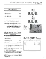
VARIABLE SPD INTERNAL

PUMP CONFIGURATION

LOOP OPTION                                        SINGLE 

PUMP CONTROL                                       FIXED

HEATING STAGE 1                                        60%

COOLING STAGE 2                                        75%

COOLING STAGE 1                                       50%

COOLING STAGE 2                                       70%

 PREVIOUS                                        SELECT 

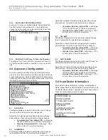
Two 
connections 
on DXM2 
board to allow 
for multi-unit 
installation

Or

3.5 VALVE 

CONFIGURATION

Confi gure temperature differentials at the thermostat for 
vFlow™ units with a motorized modulating valve.

Adjust the Valve Confi guration settings using the up/down 
arrow buttons.  Press the center button to select each item.


•  Heating Delta T (default stored in control) – 


valid range:  4 to 12ºF (in 1ºF increments)


•  Cooling Delta T (default stored in control) – 


valid range:  9 to 20ºF (in 1ºF increments)

NOTE 1: 

Minimum and Maximum degree values are shown 

only when the control is confi gured with the appropriate 
values.

NOTE 2: 

Refer to section 3.6.3 for multi-unit confi guration 

instructions.

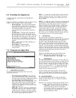
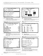
MODULATING VALVE

CONFIGURATION

OFF POSITION                                               0.0

VALVE CONTROL DELTA T

HEATING DELTA T                                           7 F

COOLING DELTA T                                        10 F

MAXIMUM HEAT LWT                                    80 F

MINIMUM COOL LWT                                    40 F

 PREVIOUS                                        SELECT 

For certain commercial multi-unit applications, the modulating 
valve can be kept slightly open by choosing an off position 
value between 3.3-4.0.

NOTE: 

Off position 0.0 means that the value is fully closed 

when the unit is not operating.

3.6 MULTI-UNIT 

CONFIGURATION

If multiple units are connected to one ATC thermostat upon 
unit start-up, the thermostat will automatically register the 
serial numbers of all units connected to it.

NOTE

: Multiple units may be connected directly to the ATC 

thermostat or connected to one another in series, as shown 
by the fi gure below.

3.6.1 MULTI-UNIT 

AIRFLOW 

SELECTION

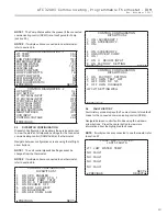
In section 3.1, when an installer selects “Airfl ow Selection” 
from the System Confi guration menu, the installer may 
choose the unit to confi gure by the last 4 digits of its serial 
number from the following screen.

AIRFLOW SELECTION

TT026                                       S N - - - - - 1 2 3 4

TT026                                       S N - - - - - 5 6 7 8

TT038                                       S N - - - - - 9 0 1 2

 PREVIOUS                                        SELECT 

Summary of Contents for iGate ATC32U03

Page 1: ...Access 6 2 2 Thermostat Configuration 6 3 0 System Configuration 7 3 1 Airflow Selection 7 3 2 Option Selection 7 3 3 Unit Configuration 8 3 4 Pump Configuration 8 3 5 Valve Configuration 9 3 6 Multi...

Page 2: ...This page was intentionally left blank...

Page 3: ...need not be leveled for proper operation and mark wall through 2 mounting holes 5 Drill two 3 16 in mounting holes in wall where marked Note Mounting holes on thermostat are designed to fit on a hori...

Page 4: ...ontrol algorithm must be configured for Differential control to access the Differential settings by installer 1 1 2 HUMIDITY OFFSET If you find that the Humidity level displayed on the thermostat does...

Page 5: ...erature at the time when Demo Mode is entered The unit will operate in heating or cooling based upon the following algorithm 1 3 3 EXITING DEMO MODE To exit demo mode remove power to the thermostat St...

Page 6: ...onds while the thermostat is in OFF Mode 2 2 THERMOSTAT CONFIGURATION Upon initial power up the communicating thermostat will prompt the installer for the thermostat configuration settings Model numbe...

Page 7: ...e center button to select each item Airflow Settings defaults stored in control valid range obtained from control in 25 CFM increments Blower Off Delay default 60 seconds valid range 0 to 255 seconds...

Page 8: ...OP CONFIG VS PUMP SELECT OPTION PREVIOUS SAVE 3 4 PUMP CONFIGURATION vFlow vs internal flow control pump can be controlled either through temperature differential Delta T or can be set to specific spe...

Page 9: ...figuration instructions MODULATING VALVE CONFIGURATION OFF POSITION 0 0 VALVE CONTROL DELTA T HEATING DELTA T 7 F COOLING DELTA T 10 F MAXIMUM HEAT LWT 80 F MINIMUM COOL LWT 40 F PREVIOUS SELECT For c...

Page 10: ...ts Calendar Time default Off valid range Off 3 to 24 months in 3 month increments 4 3 UV LAMP This feature displays an alert to remind the user to change the UV lamps after the selected time has passe...

Page 11: ...ershooting the temperature setpoint adjust the Anticipator value up to reduce thermostat sensitivity If the thermostat is undershooting the temperature setpoint adjust the Anticipator value down to in...

Page 12: ...the center button to save changes Smart Heat Staging default Off options OFF 5 120 minutes in 5 minute increments 7 6 ELECTRIC HEAT LOCKOUT Electric heat lockout keeps electric heat turned off if the...

Page 13: ...3 1 ON FACTORY SETTING 2 OFF HWG TEST OFF 3 OFF HWG SP 125 4 OFF HWG DISABLED JW3 LT1 SETTING WELL PREVIOUS 9 3 DIPSWITCH CONFIGURATION Dipswitch Configuration mode allows the service personnel to vie...

Page 14: ...9 7 9 4 4 Configuration Conditions Displays the status of all dipswitch settings that were recorded at the time the fault occurred NOTE If multiple units are connected to one thermostat refer to secti...

Page 15: ...onnected directly to the ATC thermostat or connected to one another in series as shown by the figure below CONTROL DIAGNOSTICS TT026 S N 1 2 3 4 TT026 S N 5 6 7 8 TT038 S N 9 0 1 2 PREVIOUS SELECT TT0...

Page 16: ...imateMaster s opinion or commendation of its products ClimateMaster Inc 2012 97B0055N03 7300 S W 44th Street Oklahoma City OK 73179 Phone 405 745 6000 Fax 405 745 6058 climatemaster com Rev November 3...

Reviews: