ClimateMaster Flow Controller 3 Installation, Operation & Maintenance Instructions Manual Download Page 20

Flow Controller 3

R e v. : F e b u r a r y   9 , 2 0 1 6

20

G e o t h e r m a l   H e a t   P u m p   S y s t e m s

Geothermal Closed Loop Design

In smaller loops of two tons [7 kW] or less, the reasons for 

using parallel loops as listed above may be less obvious. 

In these cases, series loops can have some additional 

advantages:

•  No header - fittings tend to be more expensive and 

require extra labor and skill to install.

•  Simple design - no confusing piping arrangement for 

easier installation by less experienced installers.

Parallel Loop Design

Loop Configuration - Determining the style of loop primarily 

depends on lot (yard) size and excavation costs. For instance, 

a horizontal 1 pipe loop will have significantly (400%) more 

trench than a horizontal 6 pipe loop. However, the 6 pipe will 

have about 75% more feet of pipe. Therefore, if trenching 

costs are higher than the extra pipe costs, the 6 pipe loop 

is the best choice. Remember that labor is also a factor in 

loop costs. The 6 pipe loop could also be chosen because 

of the small available space. Generally a contractor will know 

after a few installations which configuration is the most cost 

effective. This information can be applied to later installations 

for a more overall cost effective installation for the particular 

area. Depth of the loop in horizontal systems generally does 

not exceed 5 feet [1.5 meters] because of trench safety issues 

and the sheer amount of soil required to move. In vertical 

systems economic depth due to escalating drilling costs in 

rock can sometimes require what is referred to as a parallel-

series loop. That is, a circuit will loop down and up through 

two consecutive bores (series) to total the required circuit 

length. Moisture content and soil types also effect the earth 

loop heat exchanger design. Damp or saturated soil types will 

result in shorter loop circuits than dry soil or sand.

Loop Circuiting - Loops should be designed with a 

compromise between pressure drop and turbulent flow 

(Reynold’s Number) in the heat exchange pipe for heat 

transfer. Therefore the following rules should be observed 

when designing a loop:

•  3 gpm per ton [3.23 l/m per kW] flow rate (2.25 gpm per 

ton [2.41 l/m per kW] minimum). In larger systems 2.5 to 

2.7 gpm per ton [2.41 to 2.90 l/m per kW] is adequate in 

most cases. Selecting pumps to attain exactly 3 gpm per 

ton [3.23 l/m per kW] is generally not cost effective from 

an operating cost standpoint.

•  One circuit per nominal equipment ton [3.5 kW] with 

 3/4” IPS and 1” IPS circuit per ton [3.5 kW]. This rule can 

be deviated by one circuit or so for different  

loop configurations.

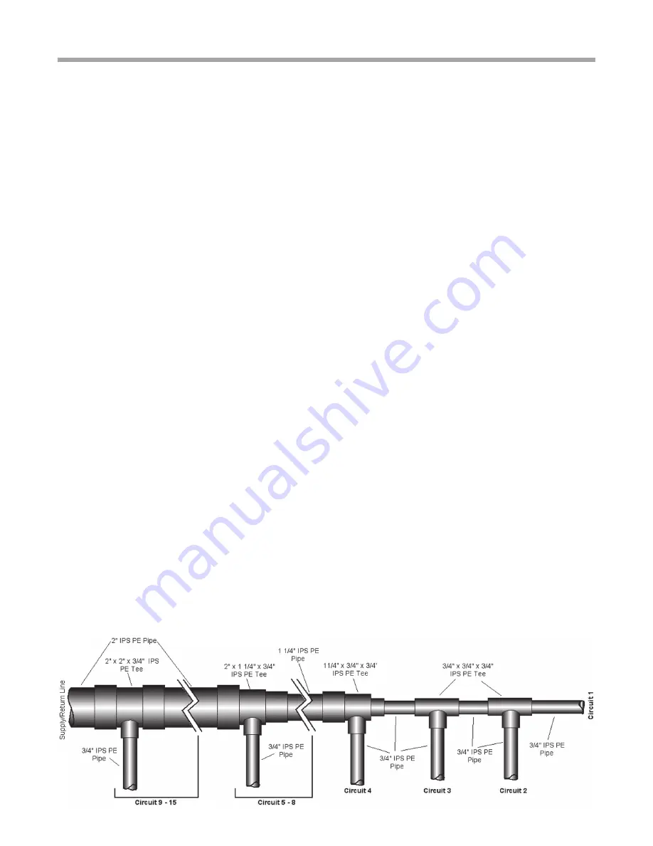
Header Design - Headers for parallel loops should be 

designed with two factors in mind, the first is pressure 

drop, and the second is ability to purge all of the air from 

the system (“flushability”). The header shown in Figure 13A 

is a standard header design through 15 tons [52.8 kW] for 

polyethylene pipe with 2” supply and return runouts. The 

header shown in Figure 13B is a standard header design 

through 5 tons [17.6 kW] for polyethylene pipe using 1-1/4” 

supply and return runouts. Notice the reduction of pipe from 

2” IPS supply/return circuits 15 to 8 to 1-1/4” IPS pipe for 

circuits 7 to 4 to 3/4” IPS to supply circuits 3, 2, and 1. This 

allows minimum pressure drop while still maintaining 2 fps 

[0.6 m/s] velocity throughout the header under normal flow 

conditions (3 gpm/ton [3.23 l/m per kW]), thus the header 

as shown is self-flushing under normal flow conditions. This 

leaves the circuits themselves (3/4” IPS) as the only section 

of the loop not attaining 2 fps [0.6 m/s] flush velocity under 

normal flow conditions (3 gpm per ton [3.23 l/m per kW], 

normally 3 gpm [11.4 l/m] per circuit). Pipe diameter 3/4” IPS 

requires 3.8 gpm [14.4 l/m] to attain 2 fps [0.6 m/s] velocity. 

Therefore, to calculate flushing requirements for any PE loop 

using the header styles shown, simply multiply the number 

of circuits by the flushing flow rate of each circuit (3.8 gpm 

for 2 fps velocity [14.4 l/m for 0.6 m/s]). For instance, on a 5 

circuit loop, the flush flow rate is 5 circuits x 3.8 gpm/circuit 

= 19 gpm [5 circuits x 14.4 l/m per circuit = 72 l/m or 1.2 l/s]. 

NOTICE

: Whenever designing an earth loop heat exchanger, 

always assume the worst case, soil and moisture conditions 

at the job site in the final design. In other words, if part of the 

loop field is saturated clay, and the remainder is damp clay, 

assume damp clay for design criteria.

Headers that utilize large diameter pipe feeding the last 

circuits should not be used. PE 1-1/4” IPS pipe requires 9.5 

Summary of Contents for Flow Controller 3

Page 1: ...Mounting 4 Piping Installation 5 Electrical Wiring 9 Flushing the Earth Loop 10 Antifreeze Selection 13 Antifreeze Charging 15 Low Temperature Cutout Selection 16 Flow Controller Pump Curves 17 Pump...

Page 2: ...Flow Controller 3 R ev F e bu rary 9 2016 2 Geothermal Heat Pump Systems This page has intentionally been left blank...

Page 3: ...or two Grundfos pump models UP26 99 or UP26 116 are available for a variety of unit flow rates and loop layouts Flow Controllers are designed for systems that require water flow rate of up to 20 U S G...

Page 4: ...ting Stud Wall Mounting on stud wall with or without drywall can be accomplished by using the two supplied lag bolts through the top and bottom center holes directly into the studs as shown in Figure...

Page 5: ...D 1 2 12 7 mm wall 1 IPS PE 1 1 4 31 8 mm ID 1 2 12 7 mm wall 1 1 4 IPS PE 1 5 8 41 3 mm ID 1 2 12 7 mm wall 2 IPS PE 2 3 8 60 3 mm ID 1 2 12 7 mm wall Table 2 Typical Piping Insulation Materials AFC4...

Page 6: ...s typically connected using the hose kit AHK5EC which contains all fittings necessary for connection between the Flow Controller and the unit as shown in Figure 5 In multiple unit systems PE piping ma...

Page 7: ...should not be used PE pipe or SCH80 PVC should be used for lengths greater than 10 ft 3 meters 4 All units must include P T ports for flow rate measure and balancing 5 Use optional field installed lo...

Page 8: ...lose enough to unit to maintain short approx 10 ft 3m hose kit from Flow Controller to unit 4 All units must include P T ports for flow rate measure and balancing Multiple Units on Common Loop Field P...

Page 9: ...e phase voltage Pumps are fused through a pair of circuit breakers in the unit control box See electrical table for Flow Controller characteristics The pump slaving module is designed to allow two uni...

Page 10: ...least a 1 5 hp 1 1kW pump is needed to achieve adequate flow velocity in the loop to purge air and dirt particles from the loop itself Antifreeze solution is used in most areas to prevent freezing All...

Page 11: ...uously mixed back into the fluid Surges of 50 psi 345 kPa can be used to help purge air pockets by simply shutting off the return valve going into the flush cart reservoir This process dead heads the...

Page 12: ...seasons and pressures will be higher in the winter months than during the cooling season This fluctuation is normal and should be considered when charging the system initially Unhook the flush cart fr...

Page 13: ...imum entering loop temperatures drop below 40 F 4 4 C or where piping will be routed through areas subject to freezing antifreeze is needed Alcohols and glycols are commonly used as antifreeze solutio...

Page 14: ...anol is not recommended because of the unknown denaturants included in the solution and their possible toxicity and damage resulting to polyethylene piping systems Denaturing agents that are petroleum...

Page 15: ...through both the unit and the loop and flush until fluid is homogenous and mixed It is recommended to run the unit in the heating and cooling mode for 15 20 minutes each to temper the fluid temperatur...

Page 16: ...ent internal damage to the port Use same gauge and thermometer to determine the differential in pressure and temperature Earth Loop Pressure The earth loop must have a slight positive pressure to oper...

Page 17: ...6 17 18 19 20 21 22 23 24 25 26 27 28 29 30 Flow Rate Head ft kPa 1 Grundfos 26 99 2 Grundfos 26 99 2 Grundfos 26 116 3 Grundfos 26 99 0 06 0 13 0 19 0 25 0 32 0 38 0 44 0 50 0 57 0 63 0 69 0 76 0 82...

Page 18: ...e with new pump insuring no foreign material has been introduced and evenly install the four Allen head mounting bolts 5 Place garden hose supply and return on flush ports as shown in Figure 12 and op...

Page 19: ...to be more forgiving of operator skill Joints are frequently required in difficult trench connections and the smaller socket fusion iron is more mobile Operators will have less of a tendency to cut co...

Page 20: ...per kW minimum In larger systems 2 5 to 2 7 gpm per ton 2 41 to 2 90 l m per kW is adequate in most cases Selecting pumps to attain exactly 3 gpm per ton 3 23 l m per kW is generally not cost effectiv...

Page 21: ...uce pressure drop problems In general 2 feet of head 6 kPa pressure drop is allowed for all earth loop fittings which would include 10 12 elbows for inside piping to the Flow Controller This allows a...

Page 22: ...ails common loop cross sections used in horizontal loops Actual number of circuits used in each trench will vary depending upon property size Use GeoDesigner software to determine the best layout Vert...

Page 23: ...is not intended for commercial loop design Figure 16 Typical Horizontal Loop Configurations Seal and protect the entry point of all earth coupling entry points into the building using conduit sleeves...

Page 24: ...when all loops are assembled before backfilling and pipe burial Closed Loop Installation Figure 18 Typical Pond Lake Loop Configurations Building Entry Figure 19 Slab on Grade Entry Detail Figure 20 R...

Page 25: ...1 40 1 86 7434 0 49 1 19 5946 12 26 82 6 63 14655 9 22 4 23 11702 3 08 2 66 9281 1 63 2 03 8110 0 57 1 30 6486 13 30 84 7 18 15876 10 60 4 58 12677 3 54 2 88 10054 1 87 2 20 8786 0 65 1 41 7027 14 12...

Page 26: ...9 22 3 87 6287 3 10 2 44 4986 1 64 1 86 4357 0 58 1 19 3485 12 30 94 6 63 8588 10 70 4 23 6858 3 59 2 66 5439 1 91 2 03 4753 0 67 1 30 3801 13 35 51 7 18 9304 12 27 4 58 7430 4 11 2 88 5892 2 18 2 20...

Page 27: ...2 44 5272 1 62 1 86 4607 0 57 1 19 3685 12 30 46 6 63 9082 10 53 4 23 7252 3 53 2 66 5752 1 87 2 03 5026 0 66 1 30 4020 13 34 97 7 18 9839 12 08 4 58 7857 4 05 2 88 6231 2 15 2 20 5445 0 75 1 41 4355...

Page 28: ...01 1 47 1 86 6380 0 51 1 19 5103 12 27 90 6 63 12577 9 61 4 23 10043 3 21 2 66 7965 1 70 2 03 6960 0 59 1 30 5567 13 32 07 7 18 13625 11 04 4 58 10880 3 69 2 88 8629 1 95 2 20 7540 0 68 1 41 6031 14 1...

Page 29: ...5 3 4 6 5 0 2 0 1 6 1 3 2 7 9 1 3 6 1 1 5 0 0 4 6 5 2 8 6 2 8 6 1 3 0 3 9 2 5 6 3 9 4 3 1 9 0 8 3 9 9 5 4 3 1 1 7 1 3 8 8 0 2 2 7 1 7 5 0 8 4 1 7 2 4 8 2 6 8 1 6 2 0 1 3 6 8 3 6 8 3 1 3 3 0 4 4 3 6 3...

Page 30: ...5 99 3 17 7308 5 79 3 17 8363 10 7 02 3 52 8997 8 09 3 52 5095 7 20 3 52 8115 6 96 3 52 9286 11 8 29 3 87 9892 9 56 3 87 5602 8 51 3 87 8922 8 23 3 87 10210 12 9 65 4 23 10812 11 13 4 23 6123 9 91 4 2...

Page 31: ..._____________________________________________________________________________________ Permit number _______________ Owner s preference on location of loop __________________________ __________________...

Page 32: ...ls or rating labels have been removed or defaced 5 Products on which payment to CM or to the owner s seller or installing contractor is in default 6 Products which have not been installed and maintain...

Page 33: ...33 Flow Controller 3 Rev Febur ary 9 2 0 1 6 Notes...

Page 34: ...s and do not form the basis of any bargain between the parties but are merely ClimateMaster s opinion or commendation of its products ClimateMaster Inc 2006 97B0015N01 7300 S W 44th Street Oklahoma Ci...

Reviews: