


Disassembly
2 - 12 Removing the System Memory (RAM)
2.Disassembly
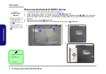
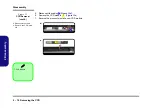
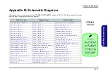
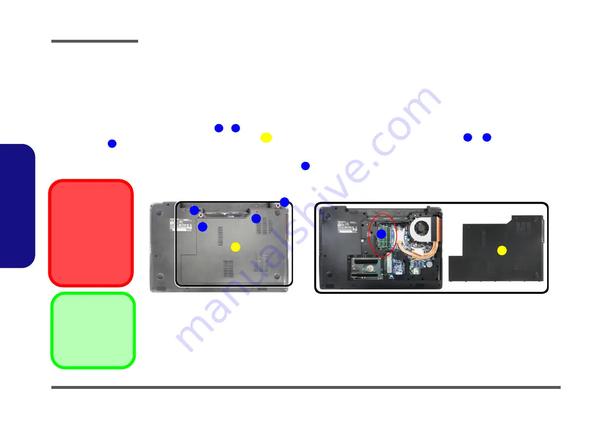
Removing the System Memory (RAM)
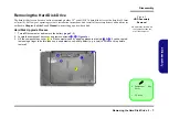
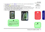
Figure 8
RAM Module
Removal
a. Remove the screws
from the component
bay cover.
b. Remove the compo-
nent bay cover. The
RAM modules will be
visible at point
on
the mainboard.
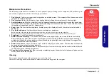
Contact Warning
Be careful not to touch
the metal pins on the
module’s connecting
edge. Even the cleanest
hands have oils which
can attract particles, and
degrade the module’s
performance.
6
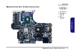
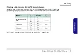
The computer has two memory sockets for 260 pin Small Outline Dual In-line Memory Modules (SO-DIMM) supporting
DDR4 up to 2133 MHz. The main memory can be expanded up to 32GB. The total memory size is automatically detected
by the POST routine once you turn on your computer.
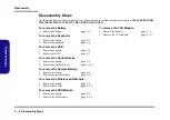
Memory Upgrade Process
3. Component Bay Cov-
er
•
2 Screws
1.
Turn
off
the computer, turn it over, and remove the battery (
2.
Remove screws
-
from the component bay cover (
).
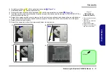
3.
Lift the component bay cover
off the computer case by applying pressure at points
&
; if you have prob-
lems using a finger to do this, then use a non-abrasive, non-sharp object (e.g. a coin) to lift the cover up before
removal).
4.
The RAM modules will be visible at point
on the mainboard (
)
.
1
2
3
4
5
6
a.
b.
1
2
4
3
3
5
6
Summary of Contents for W670RCW
Page 1: ...W670RCW W670RCW1 ...
Page 2: ......
Page 3: ...Preface I Preface Notebook Computer W670RCW W670RCW1 Service Manual ...
Page 24: ...Introduction 1 12 1 Introduction ...
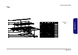
Page 45: ...Top A 3 A Part Lists Top Figure A 1 Top ...
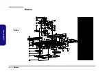
Page 46: ...A 4 Bottom A Part Lists Bottom Figure A 2 Bottom ...
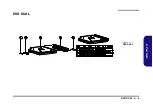
Page 47: ...DVD DUAL A 5 A Part Lists DVD DUAL Figure A 3 DVD DUAL ...
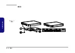
Page 48: ...A 6 HDD A Part Lists HDD Figure A 4 HDD ...
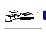
Page 49: ...2nd HDD A 7 A Part Lists 2nd HDD Figure A 5 2nd HDD ...


