


Disassembly
Removing and Installing the Processor 2 - 13
2.Disassembly
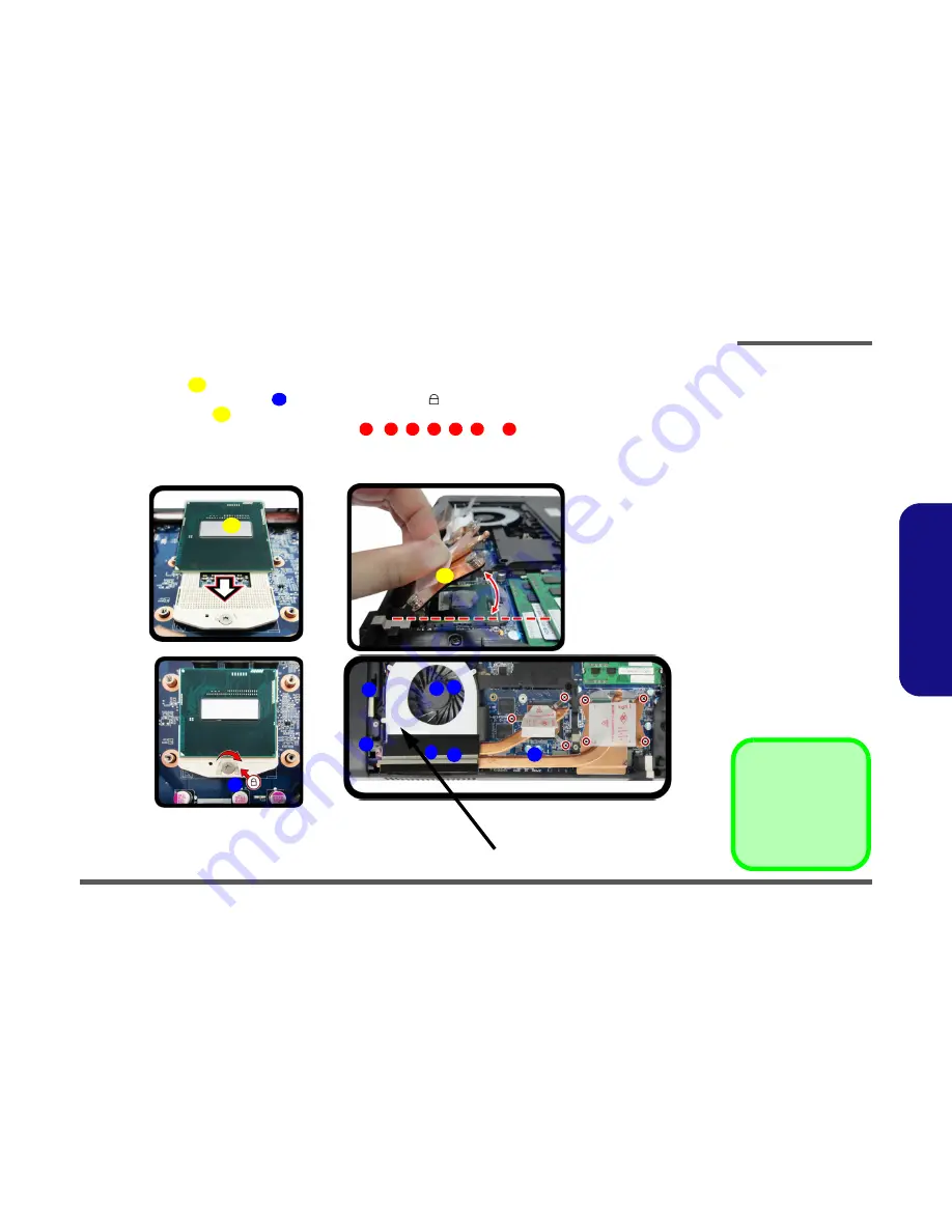
Processor Installation Procedure
1.
Insert the CPU
(
Figure 9a
), pay careful attention to the pin alignment, it will fit only one way (DO NOT FORCE
IT!), and turn the release latch
towards the lock symbol
(
Figure 9b
).
2.
Insert the heat sink
at an angle of around 30° as indicated in
Figure 9c
.
3.
Tighten the CPU heat sink screws in the order
,
, , , ,
&
(the order as indicated on the label
and
Figure 9d
).
4.
Replace the component bay cover.
A
B
C
1
2
3
4
5
6
7
45
°
b.
B
a.
c
Note
:
Tighten the screws in the order
as indicated on the label.
A
c.
d.
2
1
3
4
6
5
7
Figure 9
Processor
Installation
a. Insert the CPU.
b. Turn the release latch to-
wards the lock symbol.
c. Insert the heat sink.
d. Tighten the screws.
A. CPU
D. Heat Sink
•
7 Screws
Summary of Contents for W370ST
Page 1: ...W370ST ...
Page 2: ......
Page 3: ...Preface I Preface Notebook Computer W370ST Service Manual ...
Page 24: ...Introduction 1 12 1 Introduction ...
Page 43: ...Part Lists Top A 3 A Part Lists Top Figure A 1 Top ...
Page 44: ...Part Lists A 4 Bottom A Part Lists Bottom Figure A 2 Bottom ...
Page 45: ...Part Lists LCD A 5 A Part Lists LCD Figure A 3 LCD ...
Page 46: ...Part Lists A 6 HDD A Part Lists HDD Figure A 4 HDD ...
Page 47: ...Part Lists 2nd HDD A 7 A Part Lists 2nd HDD Figure A 5 2nd HDD ...
Page 48: ...Part Lists A 8 DVD A Part Lists DVD Figure A 6 DVD ...
Page 49: ...Part Lists COMBO A 9 A Part Lists COMBO Figure A 7 COMBO ...
Page 50: ...Part Lists A 10 A Part Lists ...


