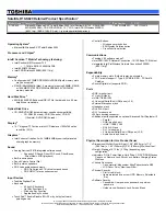
background image

Schematic  Diagrams

B - 32   USB, FAN, TP, MULTI CON 

B.Schematic Diagrams

USB, FAN, TP, MULTI CON


L I D _ S W #

1229 D02(W240HU)

1 20 2

1228 D02

L 13

*W C M2 0 12 F 2 S -S H OR T

1

4

2

3

M _B T N #

A U S B _ P N 1 _ R

F ON #

W E B _E M A I L #

W E B _W W W #

C 5 9 7

0. 1u _ 16 V _ Y 5 V _ 0 4

U S B _ P N 3 1 7
U S B _ P P 3 1 7

J_ T P 2

88 4 86 -0 8 01

1
2
3
4
5
6
7
8

R 1 3 1

*2 8m i l _0 6

C 11 4

4 7 p_ 5 0 V _N P O_ 0 4

U 38

A X 9 95 S A

V OU T

3

GN D

5

V I N

2

F ON

1

V S E T

4

GN D

6

GN D

7

GN D

8

C 2 0 5

0. 1 u _ 16 V _ Y 5 V _ 0 4

R 34 0

2 2 0 _0 4

J _ S W 2

*5 05 0 0 -01 0 41 -0 0 1L

1
2
3
4
5
6
7
8
9

1 0

C 2 9

0 . 0 1 u_ 1 6 V _X 7 R _ 0 4

R 33 9

2 2 0 _0 4

R 1 27

1 0 K _ 04

Q9
*M TN 70 0 2 Z H S 3

G

D

S

C 2 7

0 . 01 u _ 16 V _ X 7R _0 4

J _ A U D I O 1

8 72 1 3 - 14 0 0 G

1
2
3
4
5
6
7
8

10
11
12
13
14

9

C 45 6

1 0 u_ 6 . 3 V _X 5 R _ 0 6

R 20 2

4 . 7K _ 0 4

J_ F A N 1

8 5 20 5 -03 7 0 1

1
2
3

C 1 1 3

1 u _6 . 3 V _ Y 5 V _0 4

C 1 15

4 7 p _5 0 V _ N P O _ 0 4

J_ S W 1

88 4 8 6- 0 8 01

1
2
3
4
5
6
7
8

R 12 9

1 0 K _ 04

C 22 3

0 . 0 1 u_ 1 6 V _X 7 R _ 0 4

5 V S

3. 3 V S

5 V S _ F A N

5 V S _ F A N

5 V S

5 V S _ TP

5 V S

3. 3 V

3 . 3V S

V I N

3. 3 V

3 . 3 V S

C P U _ F A N

2 8

5 V

A U D G

M_ B T N #

3 2

T P _ C L K

2 8

T P _ D A T A

2 8

C P U _ F A N S E N

2 8

W E B _ W W W # 2 8

L I D _ S W # 1 1 , 2 8

W E B _ E MA I L # 2 8

A P _ K E Y #

28

A P _ ON

32

M I C 1 -L

3 0

H P _ S E N S E

30

M I C _ S E N S E

30

H E A D P H O N E -L

30

H E A D P H O N E -R

30

M I C 1 -R

3 0

U S B _ P P 9

17

U S B _ P N 9

17

S P K OU T R -

30

S P K OU T R +

30

5V

23 , 2 7 , 32 , 3 4 , 35 , 3 6

V I N

1 1 , 3 2, 3 3 , 34 , 3 5 , 36 , 3 7 , 38 , 3 9

3. 3 V

2 , 3 , 8, 1 1 , 1 3, 1 5 , 1 7, 1 9 , 2 0, 2 2 , 23 , 2 7 , 29 , 3 2 , 34 , 3 6

5V S

1 1 , 1 2, 1 9 , 20 , 2 6 , 30 , 3 2 , 37 , 3 8

3. 3 V S

3 , 9 , 1 0, 1 1 , 1 2, 1 3 , 1 4, 1 5 , 1 6, 1 7 , 1 8, 1 9 , 2 0, 2 3 , 2 4, 2 5 , 26 , 2 8 , 29 , 3 0 , 32 , 3 7

01 0 1   D 0 2

C 5 46

*

0.

1u_50

V

_Y

5

V

_0

6

Audio B'd CONN

A U S B _ P P 1 _ R

FAN CONTROL

U 5 0

*A X 9 9 5B

V OU T

1

GN D

5

V I N

3

F ON #

4

V S E T

6

GN D

2

F O N #

AX9 95 B &   APE8 87 2

Co-L ayo ut

PN:APE88 74

2n d Sou rce

5 V S _ F A N

5 V S

C P U _ F A N

28

CLICK B'd & FP CONN

POWER SWITCH B'd CONN

3

JFAN

80 mil

W 24 0 H U    3 17 D E 04 P S A7 A 2 C

W 25 0 H U    1 -2 8 4 -8 0 0 28 1 - 1

Port 1

D D _ O N #

32 , 3 4

C 4 9 3

*0 . 1 u_ 1 6 V _Y 5 V _0 4

+

C 4 88

1 0 0 u_ 6 . 3V _B _ B

L 6 2
H C B 1 6 08 K F -1 2 1 T2 5

C 5 0 1

0 . 1 u_ 1 6 V _Y 5 V _0 4

J _ U S B _ 1

3 1 7 D E 0 4 P S A 7 A 2C

V +

1

G

ND1

GN

D

1

D A TA _ L

2

D A TA _ H

3

GN D

4

GN

D

2

GN

D

2

GN

D

4

GN

D

4

GN

D

3

GN

D

3

C 49 1

1 0 u_ 6 . 3 V _ X5 R _ 0 6

C 49 2

0 . 1 u _1 6 V _Y 5 V _0 4

U 4 0

R T9 7 15 B G S / S Y 6 2 88 D F A C

V O U T 1

6

V O U T 3

8

V I N 2

3

V I N 1

2

V O U T 2

7

G N D

1

E N #

4

F L G#

5

C 9 4

0 . 1 u _1 6 V _ Y 5 V _ 04

R 5 2 4

*0 _0 4

U S B V C C

1

U S B V C C

5 V

G_ U S B V C C

U S B _ P P 1

1 7

U S B _ P N 1

1 7

U S B _ O C # 01

17

CO-LAY USB 3.0 J_USB2

F L G#

100 MIL

USB 2.0

U S B V C C

2 7

3 . 3V S

3 . 3V S _ F P

C 5 96

1U _1 0 V _ 06

.

L5 0

H C B 1 6 08 K F -1 2 1T 2 5

C 5 4 7

*0.

1

u_16V

_Y

5V

_04

11 1 9 -2

If system has AP ON function, uses J_SW1 
If system has no AP ON function, uses J_SW2

M _B T N #

A P _ K E Y #

CLOSE TO J_SW1

A P _ O N

A P _ K E Y #

L I D _ S W #

W E B _ W W W #

2 0m il

W E B _ E M A I L#

2 0mi l

1.1A 60mils

S P K _H P #

H E A D P H ON E -LL
M I C _ S E N S E

H E A D P H ON E -R R

H P _ S E N S E

S P K OU T R +
S P K OU T R -

Sheet 31 of 46

USB, FAN, TP, 

MULTI CON

Summary of Contents for W243HWQ Series

Page 1: ...W243HWQ W244HWQ Series ...

Page 2: ......

Page 3: ...Preface I Preface Notebook Computer W243HUQ W244HUQ Service Manual ...

Page 4: ...hole or in part be reproduced translated transmitted or reduced to any machine readable form without prior consent from the vendor manufacturer or creators of this publica tion except for copies kept by the user for backup purposes Brand and product names mentioned in this publication may or may not be copyright s and or registered trademarks of their respective companies They are mentioned for id...

Page 5: ...icing and or upgrading components of the W243HWQ W244HWQ series notebook PC The following information is included Chapter 1 Introduction provides general information about the location of system elements and their specifications Chapter 2 Disassembly provides step by step instructions for disassembling parts and subsystems and how to upgrade elements of the system Appendix A Part Lists Appendix B ...

Page 6: ...port a gas leak in the vicinity of the leak 4 Use only the power cord and batteries indicated in this manual Do not dispose of batteries in a fire They may explode Check with local codes for possible special disposal instructions 5 This product is intended to be supplied by a Listed Power Unit with an AC Input of 100 240V 50 60Hz DC Output of 19V 3 42A or 18 5V 3 5A 65W minimum AC DC Adapter CAUTI...

Page 7: ... down properly and don t forget to save your work Remember to periodically save your data as data may be lost if the battery is depleted Do not expose the computer to any shock or vibration Do not place it on an unstable surface Do not place anything heavy on the computer Do not expose it to excessive heat or direct sunlight Do not leave it in a place where foreign matter or mois ture may affect t...

Page 8: ... its purpose If you do not have access to a compatible outlet have a qualified electrician install one When you want to unplug the power cord be sure to disconnect it by the plug head not by its wire Make sure the socket and any extension cord s you use can support the total current load of all the connected devices Before cleaning the computer make sure it is disconnected from any external power ...

Page 9: ...ur hands or metal objects Battery Guidelines The following can also apply to any backup batteries you may have If you do not use the battery for an extended period then remove the battery from the computer for storage Before removing the battery for storage charge it to 60 70 Check stored batteries at least every 3 months and charge them to 60 70 Battery Disposal The product that you have purchase...

Page 10: ...rals you want to use with the computer e g keyboard and mouse to their ports 5 Attach the AC DC adapter to the DC In jack at the rear of the computer then plug the AC power cord into an outlet and connect the AC power cord to the AC DC adapter 6 Use one hand to raise the lid LCD to a comfortable viewing angle do not exceed 130 degrees use the other hand as illustrated in Figure 1 to support the ba...

Page 11: ... Removing the System Memory RAM 2 10 Removing and Installing a Processor 2 12 Removing the Wireless LAN Module 2 15 Removing the 3 75G Module 2 16 Removing the Keyboard 2 17 Removing the Top Case module 2 19 Part Lists A 1 Part List Illustration Location A 2 Top A 3 Bottom with 3G A 4 Bottom without 3G A 5 SATA BLU RAY COMBO A 6 SATA DVD SUPER MULTI A 7 LCD A 8 HDD A 9 Schematic Diagrams B 1 Syste...

Page 12: ...0 85VS B 37 Power V Core1 B 38 Power V Core2 VGFX B 39 AC IN CHARGER B 40 CLICK FINGER BOARD B 41 AUDIO BOARD USB B 42 Power Switch LID Board B 43 EXTERNAL ODD BOARD B 44 FINGERPRINT BOARD B 45 POWER SEQUENCE B 46 POWER SEQUENCE 1 B 47 B 48 Updating the FLASH ROM BIOS C 1 To update the FLASH ROM BIOS you must C 1 Download the BIOS C 1 Unzip the downloaded files to a bootable CD DVD or USB Flash dr...

Page 13: ...al is shipped with the computer Operating systems e g Window 7 etc have their own manuals as do application softwares e g word processing and database programs If you have questions about those programs you should consult those manuals The W243HWQ W244HWQ series notebook is designed to be upgradeable SeeDisassembly on page 2 1 for a detailed description of the upgrade procedures for each specific ...

Page 14: ...CD 14 35 56cm 3 6mm HD TFT LCD OR 14 35 56cm 5 2mm HD TFT LCD Memory Two 204 Pin SO DIMM Sockets Supporting DDR3 1333MHz Memory Memory Expandable up to 8GB The real memory operating frequency depends on the FSB of the processor Video Adapter Intel HD Graphics 3000 Shared Memory Architecture of up to 1748MB MS DirectX 10 compatible BIOS One 32Mb SPI Flash ROM AMI BIOS Storage Factory Option One Cha...

Page 15: ... WLAN Module or Combo WLAN and Bluetooth Module Factory Option Slot 2 for 3 75G HSPA Module Card Reader Embedded Multi In 1 Card Reader MMC MultiMedia Card RS MMC SD Secure Digital Mini SD SDHC SDXC MS Memory Stick MS Pro MS Duo Power 6 Cell Smart Lithium Ion Battery Pack 48 84WH Factory Option 6 Cell Smart Lithium Ion Battery Pack 62 16WH Full Range AC DC Adapter AC Input 100 240V 50 60Hz DC Outp...

Page 16: ... 1 Introduction External Locator Top View with LCD Panel Open Figure 1 Top View 1 PC Camera Optional 2 LCD 3 Power Button 4 Hot Key Buttons 5 LED Status Indicators 6 Keyboard 7 Built In Microphone 8 Touchpad Buttons 9 Fingerprint Reader Optional 4 6 3 5 7 1 2 8 9 ...

Page 17: ...xternal Locator Front Right Side Views Figure 2 Front View 1 LED Power Indicators Figure 3 Right Side View 1 Microphone In Jack 2 Headphone Out Jack 3 USB 2 0 Port 4 Optical Device Drive Bay 5 Emergency Eject Hole 6 Security Lock Slot FRONT VIEW 1 RIGHT SIDE VIEW 1 2 3 5 4 6 ...

Page 18: ...on External Locator Left Side Rear View Figure 4 Left Side View 1 DC In Jack 2 External Monitor Port 3 RJ 45 LAN Jack 4 HDMI Out Port 5 USB 2 0 Port 6 Vent 7 USB 2 0 Port 8 Multi in 1 Card Reader LEFT SIDE VIEW 1 2 3 4 5 6 7 8 Figure 5 Rear View 1 Battery REAR VIEW 1 ...

Page 19: ...Locator Bottom View Figure 6 Bottom View 1 Battery 2 Component Bay Cover 3 Vent 4 Hard Disk Bay Cover 5 Speakers 6 USIM Card Cover Overheating To prevent your com puter from overhea ting make sure no thing blocks any vent while the computer is in use 2 3 1 4 3 5 5 3 3 6 3 ...

Page 20: ...Introduction 1 8 Mainboard Overview Top Key Parts 1 Introduction Mainboard Overview Top Key Parts Figure 7 Mainboard Top Key Parts 1 JMICRO JMC261 2 ITE IT8518E 3 AZALIA CODEC REALTEK ALC269 1 2 3 ...

Page 21: ... Introduction Mainboard Overview Bottom Key Parts 1 2 3 4 6 5 Figure 8 Mainboard Bottom Key Parts 1 Memory Slots DDR3 SO DIMM 2 CPU Socket no CPU installed 3 Platform Controller Hub 4 Mini Card Connector WLAN Module 5 SIMLOCK 6 3 75G HSPA Module Connector ...

Page 22: ...ard Overview Top Connectors Figure 9 Mainboard Top Connectors 1 HDMI Out Port 2 USB Port 2 0 3 Speaker Cable Connector 4 Microphone Cable Connector 5 Audio Board Connector 6 TouchPad Cable Connector 7 Keyboard Cable Connector 8 Switch Board Cable Connector 1 2 8 2 3 4 6 7 5 ...

Page 23: ...onnectors Figure 10 Mainboard Bottom Connectors 1 Battery Connector 2 ODD Connector 3 HDD Connector 4 CMOS Battery Connector 5 CPU Fan Cable Connector 6 Multi in 1 Card Reader 7 RJ 45 LAN Jack 8 External Monitor Port 9 DC In Jack 10 CCD Cable Connector 11 LCD Cable Connector 1 2 4 5 6 7 8 9 3 10 11 ...

Page 24: ...Introduction 1 12 1 Introduction ...

Page 25: ...isassembly process easier each section may have a box in the page margin Information contained under the figure will give a synopsis of the sequence of procedures involved in the disassembly procedure A box with a lists the relevant parts you will have after the disassembly process is complete Note The parts listed will be for the dis assembly procedure listed ONLY and not any previous disassembly...

Page 26: ...ng the connection make sure th e connector is oriented in the same way The pin1 side is usually not indicated Pressure sockets for multi wire connectors To release this connector type grasp it at its head and gently rock it from side to side as you pull it out Do not pull on the wires themselves When replacing the connection do not try to force it The socket only fits one way Pressure sockets for ...

Page 27: ... Do not pull on the wire 6 Peripherals Turn off and detach any peripherals 7 Beware of static discharge ICs such as the CPU and main support chips are vulnerable to static electricity Before handling any part in the computer discharge any static electricity inside the computer When handling a printed circuit board do not use gloves or other materials which allow static electricity buildup We sugge...

Page 28: ...ge 2 5 2 Remove the system memory page 2 10 To remove and install a Processor 1 Remove the battery page 2 5 2 Remove the processor page 2 12 3 Install the processor page 2 14 To remove the Wireless LAN Module 1 Remove the battery page 2 5 2 Remove the WLAN module page 2 15 To remove the 3 75G Module 1 Remove the battery page 2 5 2 Remove the 3 75G module page 2 15 To remove the Keyboard 1 Remove t...

Page 29: ...tch in the direction of the arrow Figure 1a 3 Slide the latch in the direction of the arrow and hold it in place Figure 1a 4 Slide the battery in the direction of the arrow Figure 1b 3 Battery 1 2 6 3 4 Figure 1 Battery Removal a Slide the latch and hold it in place b Slide the battery in the di rection of the arrow a b 3 4 2 1 ...

Page 30: ...ss 1 Turn off the computer and remove the battery page 2 5 2 Locate the hard disk bay cover and remove screws Figure 2a Figure 2 HDD Assembly Removal a Locate the HDD bay cover and remove the screws 2 S crews 1 2 a HDD System Warning New HDD s are blank Before you begin make sure You have backed up any data you want to keep from your old HDD You have all the CD ROMs and FDDs required to install yo...

Page 31: ...and the mylar cover from the hard disk Figure 3e 7 Reverse the process to install a new hard disk do not forget to replace all the screws and covers 6 3 4 5 6 9 10 11 4 b c e 5 3 11 10 d 6 7 8 9 3 HDD Bay Cover 10 Mylar Cover 11 HDD 4 S crews Figure 3 HDD Assembly Removal cont d b Remove the HDD bay cover c Grip the tab and slide the HDD in the direction of the arrow d Lift the HDD assembly out of...

Page 32: ...re 4b 5 Remove the screw at point and use a screwdriver to carefully push out the optical device at point Fig ure 4c 6 Insert the new device and carefully slide it into the computer the device only fits one way DO NOT FORCE IT The screw holes should line up 7 Restart the computer to allow it to automatically detect the new device Figure 4 Optical Device Removal a Remove the screws b Remove the cov...

Page 33: ...mputer remove the battery and remove the ODD page 2 5 2 Carefully unsnap the ODD Bezel from ODD in the direction of the arrow 3 Snap the bezel onto the ODD at points and Figure 5 ODD Bezel a Unsnap the ODD Bezel in the direction of the ar row b Snap the bezel onto the ODD at points and 2 3 4 1 2 1 a 2 3 4 b 4 3 1 ODD Bezel ...

Page 34: ...on indicated by the arrows Figure 6b 4 The RAM module will pop up Figure 6c and you can then remove it 5 Pull the latches to release the second module if necessary 6 Insert a new module holding it at about a 30 angle and fit the connectors firmly into the memory slot 7 The module s pin alignment will allow it to only fit one way Make sure the module is seated as far into the slot as it will go DO ...

Page 35: ...he bay cover Note that there are four cover pins which need to be aligned with slots in the case to insure a proper cover fit before screwing down the bay cover Figure 7d 10 Restart the computer to allow the BIOS to register the new memory configuration as it starts up 5 8 d 5 6 7 8 Figure 7 RAM Module Removal cont d d Properly re insert the bay cover pins ...

Page 36: ...e visible at point Figure 8a 3 Loosen the CPU heat sink screws in the order the reverse order as indicated on the label Figure 8a 4 Grip the heat sink tab and carefully lift the heat sink up and off the computer Figure 8b A 3 2 1 4 Figure 8 Processor Removal a The CPU heat sink will be visible at point Remove the screws from the CPU heatsink b Grip the heat sink tab and carefully lift the heat sin...

Page 37: ...rocess to install a new CPU 8 When re inserting the CPU pay careful attention to the pin alignment it will fit only one way DO NOT FORCE IT 5 6 Figure 9 Processor Removal cont d c Turn the release latch to unlock the CPU d Lift the CPU out of the socket c d Caution The heat sink and CPU area in general contains parts which are subject to high temperatures Allow the area time to cool before remov i...

Page 38: ...k as indicated in Figure 10d 4 Tighten the CPU heat sink screws in the order the order as indicated on the label and Figure 10d 5 Replace the component bay cover don t forget to replace the fan cable and tighten the screws page 2 9 A B C D 1 2 3 b B a D 1 3 2 Note Tighten th e scre ws in the order as indi cated on the label C A c d Figure 10 Processor Installation a Insert the CPU b Turn the relea...

Page 39: ...gure 11a 3 Carefully disconnect the cable and then remove the screw Figure 11b 4 The Wireless LAN module Figure 11c will pop up and you can remove it from the computer Figure 11d Figure 11 Wireless LAN Module Removal a Locate the WLAN b Disconnect the cable and remove the screw c The WLAN module will pop up d Remove the Wireless LAN module Note Make sure you reconnect the antenna cable to the 1 2 ...

Page 40: ... on the mainboard 3 Carefully disconnect the cable then remove the screw from the module socket 4 The 3 75G module will pop up 5 Lift the 3 75G module Figure 12d up and off the computer Figure 12 3 75G Module Removal a Remove the cover b Disconnect the cable and remove the screw c The 3 75G module will pop up d Lift the 3 75G module out 1 2 3 4 4 b a d 2 3 4 1 c 1 4 3 75G Module 1 S crew ...

Page 41: ... bottom of the computer and use the Eject Pin Tool to carefully push out the key board at point 3 Carefully lift the keyboard up being careful not to bend the keyboard ribbon cable Figure 13 Keyboard Removal a Remove screws from the bottom of the computer and use the Eject Pin Tool to push out the key board at point b Carefully lift the keyboard up 3 4 Keyboard 2 S crews 1 2 3 a c 1 3 2 b 4 ...

Page 42: ...omputer 5 6 Figure 14 Keyboard Removal cont d c Carefully lift the key board up and disconnect the keyboard ribbon ca ble from the locking col lar socket d Remove the keyboard Re Inserting the Keyboard When re inserting the keyboard firstly align the four keyboard tabs at the bottom Figure 14d at the bottom of the key board with the slots in the case 6 Keyboard 4 Keyboard Tabs 5 c d 6 4 ...

Page 43: ...2 17 2 Remove screws and carefully disconnect the cables from the Top Case module 3 Remove screws from the bottom of the computer and use the Eject Pin Tool to carefully push out the hinge cover at point Figure 15 Top Case module Removal a Remove screws and the cables b Remove screws from the bottom of the computer and use the Eject Pin Tool to push out the key board at point 27 6 Top Case module ...

Page 44: ...4 Carefully lift up the hinge cover off the computer 5 Carefully unsnap the top case from computer at point Figure 16 Top Case module Removal cont d c Remove the hinge cov er d Remove the top case module 28 Hinge cover 29 TopCase module 28 28 28 c 29 30 29 30 d ...

Page 45: ...rs Your organization may use a different system so be sure to cross check any relevant documentation Note Some assemblies may have parts in common especially screws However the part lists DO NOT in dicate the total number of duplicated parts used Note Be sure to check any update notices The parts shown in these illustrations are appropriate for the system at the time of publication Over the produc...

Page 46: ...e indicates where to find the appropriate part list illustration Table A 1 Part List Illustration Location Part W243HWQ W244HWQ Top page A 3 Bottom w 3G page A 4 Bottom w o 3G page A 5 SATA BLU RAY COMBO page A 6 SATA DVD SUPER MULTI page A 7 LCD page A 8A HDD page A 9 ...

Page 47: ...Top A 3 A Part Lists Top 灰色 黑色 Figure A 1 Top ...

Page 48: ...A 4 Bottom with 3G A Part Lists Bottom with 3G Figure A 2 Bottom with SIM W240HUQ W241HUQ W245HUQ Series ...

Page 49: ...Bottom without 3G A 5 A Part Lists Bottom without 3G Figure A 3 Bottom without 3G ...

Page 50: ...A 6 SATA BLU RAY COMBO A Part Lists SATA BLU RAY COMBO Figure 4 SATA BLU RAY COMBO ...

Page 51: ...SATA DVD SUPER MULTI A 7 A Part Lists SATA DVD SUPER MULTI Figure 5 SATA DVD SUPER MULTI ...

Page 52: ...A 8 A Part Lists LCD 銘板 Figure A 6 LCD ...

Page 53: ...HDD A 9 A Part Lists HDD 無鉛 無鉛 Figure A 7 HDD ...

Page 54: ...A 10 A Part Lists ...

Page 55: ...Page B 25 AUDIO BOARD USB Page B 42 PROCESSOR RESERVED Page B 9 INTEL LAN 82579 Page B 26 Power Switch LID Board Page B 43 DDR3 SO DIMM_0 Page B 10 LAN 82579 SATA HDD ODD Page B 27 EXTERNAL ODD BOARD Page B 44 DDR3 SO DIMM_1 Page B 11 USB3 0 NEC USB CHARGER Page B 28 FINGERPRINT BOARD Page B 45 LVDS Inverter Page B 12 KBC ITE IT81518 Page B 29 POWER SEQUENCE Page B 46 HDMI CRT Page B 13 LED MDC BT...

Page 56: ...d ec E C 0 5 1 1 SO CK ET 5V 3V 5VS 3VS 1 5VS 1 5VS_CPU 1 5 CRT SWITC H L VD S S WI TC H USB2 0 VDD3 VDD5 DMI 4 32 768 KHz W 83 L7 71 AW G JMICRO 6 7 1 E5 1Q S D 02 SATA I II 3 0Gb s REALTEK ALC269 800 1067 MHz DDR3 1 5V 14 14 1 6mm 33 MHz TH ER MA L SE NS OR 100 MHz POWER SWITCH BOARD 810 602 1703 S MA RT FA N U SB 5 PROCESSOR 37 5 37 5 mm JMC261 C CougarPoint Platform Controller Hub PCH 25x25x0 ...

Page 57: ... F 2 7 P E G _ TX 1 3 D2 8 P E G _ TX 1 4 F 2 6 P E G _ TX 1 5 E 2 5 P E G_ T X 0 M2 8 P E G_ T X 1 M3 3 P E G_ T X 2 M3 0 P E G_ T X 3 L 31 P E G_ T X 4 L 28 P E G_ T X 5 K 3 0 P E G_ T X 6 K 2 7 P E G_ T X 7 J 29 P E G_ T X 8 J 27 P E G_ T X 9 H2 8 P E G _T X 1 0 G2 8 P E G _T X 1 1 E 2 8 P E G _T X 1 2 F 2 8 P E G _T X 1 3 D2 7 P E G _T X 1 4 E 2 6 P E G _T X 1 5 D2 5 e DP _ A U X C 1 5 e DP _ ...

Page 58: ... 2 1 5 K _1 _ 04 Processor Pullups Pull downs TR AC E WI DTH 1 0M IL LEN GT H 5 00 MIL S 3 3V S B U F _C P U_ R S T DDR3 Compensation Signals S M _R CO MP _ 2 S M _R CO MP _ 1 S M _R CO MP _ 0 C9 6 6 8 p_ 5 0 V _N P O_ 0 4 V DD P W R GOO D_ R X DP _ T RS T X DP _ T CL K P L T _ RS T 1 7 23 X DP _ T MS X DP _ T DI_ R C P UD RA M RS T H _ P RO CH OT _D H_ C A TE RR Buffered reset to CPU X DP _ T DO ...

Page 59: ...A _DQ5 M _A _DQ5 9 M _A _DQ6 2 M _A _DQ6 3 M _A _DQ6 0 M _A _DQ6 1 M _A _DQ9 M _A _DQ8 M _A _DQ7 M _A _DQ1 6 M _A _DQ1 5 M _A _DQ1 3 M _A _DQ1 2 M _A _DQ1 1 M _A _DQ1 0 M _A _DQ1 4 M _A _DQ1 9 M _A _DQ1 8 M _A _DQ1 7 M _A _DQ2 5 M _A _DQ2 3 M _A _DQ0 M _A _DQ2 1 M _A _DQ2 2 M _A _DQ2 0 M _A _DQ2 7 M _A _DQ2 6 M _A _DQ2 4 M _B _RA S 10 M _B _B S2 10 M _B _CA S 10 M _B _B S1 10 M _B _B S0 10 M _B _W...

Page 60: ...3 9 6 2 2 u_ 6 3 V _ X 5 R_ 0 8 C 4 0 7 2 2 u_ 6 3 V _ X 5 R_ 0 8 C 3 5 3 2 2u _ 6 3 V _ X5 R_ 0 8 V C OR E 1 0 5 VS _ V T T V CO RE 1 0 5V S _ V T T V C OR E H _ CP U_ S VID C LK _ R R8 5 0 _0 4 V CC IO _ S E N S E _ R R 38 4 0 _ 04 CAD Note H_CPU_SVIDCLK_R Place the PU resistors close to VR R3 7 9 10 _ 0 4 1 0 5 V S _V TT V C OR E R 38 3 1 0 _0 4 V SS IO _ S E N SE POWER CORE SUPPL Y P EG AND DD...

Page 61: ... 3 4 V A X G _S E NS E A K 3 5 VA X G1 A T 2 4 VA X G2 A T 2 3 VA X G3 A T 2 1 VA X G4 A T 2 0 VA X G5 A T 1 8 VA X G6 A T 1 7 VA X G7 A R2 4 VA X G8 A R2 3 VA X G9 A R2 1 VA X G1 0 A R2 0 VA X G1 1 A R1 8 VA X G1 2 A R1 7 VA X G1 3 A P 2 4 VA X G1 4 A P 2 3 VA X G1 5 A P 2 1 VA X G1 6 A P 2 0 VA X G1 7 A P 1 8 VA X G1 8 A P 1 7 VA X G1 9 A N2 4 VA X G2 0 A N2 3 VA X G2 1 A N2 1 VA X G2 2 A N2 0 V...

Page 62: ... 35 VS S130 AB 34 VS S131 AB 33 VS S132 AB 32 VS S133 AB 31 VS S134 AB 30 VS S135 AB 29 VS S136 AB 28 VS S137 AB 27 VS S138 AB 26 VS S139 Y9 VS S140 Y8 VS S141 Y6 VS S142 Y5 VS S143 Y3 VS S144 Y2 VS S145 W35 VS S146 W34 VS S147 W33 VS S148 W32 VS S149 W31 VS S150 W30 VS S151 W29 VS S152 W28 VS S153 W27 VS S154 W26 VS S155 U9 VS S156 U8 VS S157 U6 VS S158 U5 VS S159 U3 VS S160 U2 VSS U34I PZ98827 3...

Page 63: ...S VD 2 5 B 1 8 R S V D4 4 A P 3 5 RS VD 1 0 F 2 3 RS VD 5 A J 2 6 V A XG_ V AL _ SE NSE A J 3 1 V S SA X G_ V A L _ S ENS E A H 3 1 V CC _V A L_ S EN S E A J 3 3 V S S_ V A L _S ENS E A H 3 3 K E Y B 1 VCC _ DIE_ S EN S E A H 27 V CC IO_ SE L A 1 9 R S V D5 4 A N 35 R S V D5 5 A M 35 CF G 6 CF G 5 11 Defau lt x 16 Devic e 1 f unctio ns 1 and 2 disa bled 10 x 8 x8 De vice 1 fun ction 1 ena bled fun...

Page 64: ...K 0 1 0 1 CK 0 1 0 3 CK 1 1 0 2 CK 1 1 0 4 S D A 2 0 0 S C L 2 0 2 S A1 2 0 1 S A0 1 9 7 DM 0 1 1 DM 1 2 8 DM 2 4 6 DM 3 6 3 DM 4 1 3 6 DM 5 1 5 3 DM 6 1 7 0 DM 7 1 8 7 DQ S 0 1 2 DQ S 1 2 9 DQ S 2 4 7 DQ S 3 6 4 DQ S 4 1 3 7 DQ S 5 1 5 4 DQ S 6 1 7 1 DQ S 7 1 8 8 DQ S 0 1 0 DQ S 1 2 7 DQ S 2 4 5 DQ S 3 6 2 DQ S 4 1 3 5 DQ S 5 1 5 2 DQ S 6 1 6 9 DQ S 7 1 8 6 OD T 0 1 1 6 OD T 1 1 2 0 B A2 7 9 C1 0...

Page 65: ... Q1 7 4 1 D Q1 8 5 1 D Q1 9 5 3 D Q2 0 4 0 D Q2 1 4 2 D Q2 2 5 0 D Q2 3 5 2 D Q2 4 5 7 D Q2 5 5 9 D Q2 6 6 7 D Q2 7 6 9 D Q2 8 5 6 D Q2 9 5 8 D Q3 0 6 8 D Q3 1 7 0 D Q3 2 1 29 D Q3 3 1 31 D Q3 4 1 41 D Q3 5 1 43 D Q3 6 1 30 D Q3 7 1 32 D Q3 8 1 40 D Q3 9 1 42 D Q4 0 1 47 D Q4 1 1 49 D Q4 2 1 57 D Q4 3 1 59 D Q4 4 1 46 D Q4 5 1 48 D Q4 6 1 58 D Q4 7 1 60 D Q4 8 1 63 D Q4 9 1 65 D Q5 0 1 75 D Q5 1 1...

Page 66: ...S L0 N 16 LID _ S W 28 3 1 BLO N 1 6 AL L _SY S_ PW RG D 15 2 8 37 MU X_ 0 N L VDS LC LK P 16 BK L_ EN 2 8 SB_ BL ON 18 PLVDD HI LVDS 3 3V 3A HI eDP 3 3V 3A LOW eDP 5V 3A L2 HCB 16 0 8KF 12 1 T2 5 C5 17 0 1 u _5 0 V _ Y 5V _0 6 Q4 7 P2 0 0 3EV G 4 6 2 5 7 3 1 8 C5 8 7 0 1 u_ 5 0V _Y 5V_ 0 6 B L O N 2 A P _ DD C_ DAT A 1 6 3 A R N1 2 0 _8 P4 R_ 0 4 1 2 3 4 5 6 7 8 1 A 12 30 D02 R N1 3 0 _8 P4 R_ 0 ...

Page 67: ...4 OUT _D1 22 OUT_ D1 23 OUT _D2 19 OUT_ D2 20 OUT _D3 16 OUT_ D3 17 OUT _D4 13 OUT_ D4 14 SCL_ SINK 28 SDA_ SINK 29 HPD_ SINK 30 V CC 1 2 V CC 2 11 V CC 3 15 V CC 4 21 V CC 5 26 V CC 6 33 V CC 7 40 V CC 8 46 GND 1 1 GND 2 5 GND 3 12 GND 4 18 GND 5 24 GND 7 31 GND 8 36 GND 9 37 GN D 1 0 43 GND 49 3 3VS DDCDATA HDMIB_DATA2 P CRT_ VSY NC RED BLUE GRN HSYNC VSYNC L7 F CM1 005 MF 600 T0 1 HDMIB_CL OCKP...

Page 68: ..._0 4 R4 5 9 10 0 _ 1 _ 0 4 P C H_ J T A G_ T CK _ B UF P C H_ J T A G_ T MS P C H_ J T A G_ T DO P C H_ J T A G_ T DI RTC IHDA SATA LPC SPI JTAG S ATA 6 G U3 7 A C o ug a rP o in t_ Re v _ 1 p 0 R TC X 1 A 2 0 R TC X 2 C2 0 IN TV R ME N C1 7 IN TR UD E R K 2 2 H DA _ B CL K N3 4 H DA _ S Y N C L3 4 H DA _ RS T K 3 4 H DA _ S DI N0 E 3 4 H DA _ S DI N1 G3 4 H DA _ S DI N2 C3 4 H DA _ S DO A 3 6 S A...

Page 69: ... _T X N 6_ C P CIE _T X P 6 _ C C1 7 2 0 1 u_ 1 0 V _ X 7R _ 0 4 C1 7 5 0 1 u_ 1 0 V _ X 7R _ 0 4 P C IE _ RX N 6_ IG L A N 2 5 P C IE _ T XN 6 _I GL A N 2 5 P CIE _T X P 6 _ IGL A N 2 5 P C IE _ RX P 6 _ IGL A N 2 5 R 24 8 1 0 K _ 0 4 R 25 0 1 0 K _ 0 4 X1 1 F S X 5L _ 2 5 MH Z 1 2 R 54 3 10 K _ 0 4 B T _ S B D L P D _ S P I_ INT R R 25 5 10 K _ 0 4 R 21 9 10 K _ 0 4 112 4 change for lay out R 24...

Page 70: ... V C0 8 PW 1 2 3 14 7 R 62 5 0_ 0 4 U 15 _ 3 3 V D DR 1 5 V _ P W RG D 3 4 U1 5 _3 3 V U1 5_ 3 3 V 1 8V S_ P W R GD 3 3 4 S USB 1 05V S_V TT S USPE ND 1 0 5V _ L A N_ P W R GD 35 O N A L L _S Y S _ P W RG D 1 1 28 3 7 R6 3 1 0 _ 0 4 PM _ P CH_ P W R OK 2 8 R2 5 3 10 K _ 0 4 U 1 5D 7 4 L V C0 8 P W 1 2 1 3 11 1 4 7 D E LA Y _ P W RG D 3 7 U1 5 _3 3 V S Y S _ P W RO K S L P _ S5 R 54 6 2 K _ 0 4 1 0...

Page 71: ... L _ DA TA P 3 9 L _ D DC _ CL K T 4 0 L _ D DC _ DA T A K 4 7 L _ V D D_ E N M 4 5 L V D S A _ C L K A K 3 9 L V D S A _ C L K A K 4 0 L V D S A _ D A T A 0 A N 4 8 L V D S A _ D A T A 1 A M 4 7 L V D S A _ D A T A 2 A K 4 7 L V D S A _ D A T A 3 A J 4 8 L V D S A _ D A T A 0 A N 4 7 L V D S A _ D A T A 1 A M 4 9 L V D S A _ D A T A 2 A K 4 9 L V D S A _ D A T A 3 A J 4 7 L V D S B _ C L K A F 4 ...

Page 72: ...3 4 R2 4 1 1 0K_ 0 4 SAT A_ O DD _D A 2 6 R2 5 1 1 0 K_0 4 R N5 1 0 K_ 8P 4R _ 0 4 8 1 7 2 6 5 3 4 R N4 1 0 K_ 8P 4R _ 0 4 8 1 7 2 6 5 3 4 R2 6 5 1 0 K_0 4 3 3 VS 1207 R SV D PC I U SB U 3 7E C o ug a rPo int_ R e v _ 1p 0 R SVD 2 3 AV5 R SVD 1 AY7 R SVD 2 AV7 R SVD 3 AU3 R SVD 4 BG4 R SVD 5 AT 10 R SVD 6 BC8 R SVD 7 AU2 R SVD 8 AT 4 R SVD 1 7 BB5 R SVD 1 8 BB3 R SVD 1 9 BB7 R SVD 2 0 BE8 R SVD 2 ...

Page 73: ...F _ 1 4 B F 4 9 V S S _ NC TF _ 1 5 B G 2 V S S _ NC TF _ 1 6 B G 4 8 D F _ T V S A Y 1 HP E CI_ R R 1 37 1 0 K _ 0 4 R 6 76 0 _0 4 1 05 V S _ V T T R4 8 0 1 0 K _ 0 4 1 05 V S _ V T T 2 3 5 1 9 20 3 5 3 7 V DD 3 R6 9 9 0_ 0 4 1201 R4 4 2 1 0 K _ 04 S A T A _ DE T 4 R1 7 9 1 0 K _ 04 R1 8 1 1 0K _ 0 4 TE S T_ S E T_ U P R 4 30 2 2 K _ 0 4 R4 3 5 0 _ 0 4 C RIT _ T E MP _ R E P 2 R3 1 6 0 _ 04 R 46 ...

Page 74: ... 04 R1 6 4 2 0m i l _0 4 1 05 V S 1 0 5 V S _ V CC A P L L _F DI C1 5 6 0 1 u_ 1 0 V _ X5 R _0 4 C 16 0 0 1 u_ 1 0 V _ X5 R _0 4 1 5 V S _ 1 8V S 1 5 V S _ 1 8 V S 1 5V S _1 8 V S 1 0 5 V S 3 3V S V CC A _ P LL _ E X P V CC CL K D MI 1 8 V S 1 5 V S R 14 9 2 0 m il _ 0 4 42mA 190mA 3 3V S 1 0 5V S _V TT All VCCORE 1 3A 3 3 V S 1 8 V S _ V CC T X_ L V D 5 V S All VCCIO 2 92A 266mA 266mA R 4 60 1 0K...

Page 75: ..._6 3 V _ X 5R _ 08 C1 6 7 1u _ 6 3V _Y 5V _0 4 C4 3 8 2 2u _ 6 3V _X 5 R_ 0 8 C 1 83 1 u _ 6 3V _ Y 5V _ 0 4 C1 9 2 1u _ 6 3V _Y 5V _0 4 C4 2 7 1 u_ 6 3 V _ Y 5 V _ 04 C4 1 3 0 1 u _1 0 V _ X 5R _ 04 C 4 03 4 7 u _6 3 V _ X 5R _ 06 R2 5 8 0_ 0 6 C 20 3 0 1 u _ 10 V _ X 5 R_ 0 4 C 4 36 2 20 u _ 6 3 V _ 6 3 4 2 R 24 2 10 _ 0 4 1 0 5V S _V C CA _ A _ D P L C 20 4 0 1 u_ 1 0 V _ X5 R_ 0 4 C1 9 1 0 1 u...

Page 76: ... VSS 258 F3 VSS 262 K39 VSS 263 K46 VSS 259 H46 VSS 260 K18 VSS 261 K26 VSS 331 AD47 VSS 333 B43 VSS 334 BE10 VSS 335 BG41 VSS 337 G14 VSS 338 H16 VSS 340 T36 VSS 342 BG22 VSS 343 BG24 VSS 344 C22 VSS 345 AP13 VSS 172 F45 VSS 221 H10 VSS 346 M14 VSS 347 AP3 VSS 348 AP1 VSS 349 BE16 VSS 350 BC16 VSS 351 BG28 VSS 352 BJ28 U37H CougarPoint_Rev _1p0 VSS 1 AA17 VSS 2 AA2 VSS 3 AA3 VSS 5 AA34 VSS 6 AB11...

Page 77: ... 1 0 K _ 04 CL K _ P CIE _ M INI 1 4 W L A N_ CL K R E Q 1 4 CL _ CL K _ 1 P CIE _T XN3 _ W L AN 1 4 W L A N_ D E T 2 8 CL K _ PCIE _M INI 1 4 P C IE _ RXN3 _ W L A N 14 P CIE _ T XP 3_ W L AN 1 4 1 125 P CIE _R XP 3_ W L AN 1 4 U S B _P N2 1 7 3 3 V VD D3 W L A N_ E N 2 8 2 9 U S B _P P 2 1 7 20 mil BT _ DET 2 8 2 9 KEY J _ MIN I1 8 8 91 0 5 20 4 M 0 1 CO E X 1 3 CO E X 2 5 CL K R EQ 7 GN D0 9 RE...

Page 78: ...W R _ E N 2 8 C2 4 2 0 1u _ 16 V _ Y 5 V _ 0 4 R 50 3 4 7 K _0 4 UIM _P W R UIM_ D A TA C4 8 9 2 2p _ 5 0V _ N P O_ 04 UIM _C L K S IM L OCK UIM _V P P C2 0 9 0 1u _ 16 V _ Y 5 V _ 0 4 US B _P P 5 17 US B _ P N5 17 C 4 1 u _ 6 3 V _ Y 5 V _ 04 From H8 defa ult HI 4 8 mi l 5V J _C CD1 8 52 0 5 0 5 0 01 1 2 3 4 5 C2 1 u _ 6 3 V _ Y 5 V _ 04 CC D_ DE T 5 M J_C CD1 R1 1 1 0 0K _0 4 1 CCD 5 V _ CC D C ...

Page 79: ... G D V D D 11 24 112 4 10 29 SD_ B S 112 4 20mil P in 31 3 3V S C4 42 0 1u _16 V _Y 5V _ 04 C4 43 10u _6 3V _Y 5 V_ 06 P in 3 2 P in 32 2 0mil V DDREG C1 98 0 1u _1 6V _Y 5 V_ 04 C199 10u _6 3V _X 5R_ 06 R4 27 20 mi l_ 04 P in 3 1 11 0 2 5 V 23 27 3 1 3 2 34 35 3 6 20mil LA N_ SCL R1 36 0_ 04 P CIE_ TX P4 _GL A N 1 4 CL K _P CIE_ GLA N 14 CL K_ PCIE _ GLA N 14 P CIE _T XN4 _GLA N 14 MS _INS A V D ...

Page 80: ... 2 R619 0_04 PCIE MDI SMBUS JTA G LED U47 82579LM V RSVD_VCC3P3_1 1 RSVD_VCC3P3_2 2 LAN_D ISABLE_N 3 VDD3P3_OUT 4 VDD3P3_IN 5 VCT 6 CTRL_1P0 7 VDD1P0_8 8 X TAL_OU T 9 X TAL_IN 10 VDD1P0_11 11 RBIAS 12 MDI_PLU S0 13 MD I_MINU S0 14 VDD3P3_15 15 VDD1P0_16 16 MDI_PLU S1 17 MD I_MINU S1 18 VDD3P3_19 19 MDI_PLU S2 20 MD I_MINU S2 21 VDD1P0_22 22 MDI_PLU S3 23 MD I_MINU S3 24 LED2 25 LED0 26 LED1 27 SMB...

Page 81: ... A N_ MD IN0 DL M X1 5V S 1 1 12 1 9 2 0 3 0 3 1 3 2 3 7 3 8 DL M X3 DL M X4 L MX 1 DL M X2 DL M X3 DL M X1 GIGA LAN 82579 L MX 1 GN D L 2 9 G S T 50 0 9 LF T CT 1 1 2 T D1 3 T D1 T CT 2 4 5 T D2 6 T D2 T CT 3 7 8 T D3 9 T D3 T CT 4 10 11 T D4 12 T D4 1 3 M X 4 1 4 M X 4 MC T4 1 5 1 6 MX 3 1 7 M X 3 MC T3 1 8 1 9 M X 2 2 0 MX 2 MC T2 2 1 2 2 MX 1 2 3 MX 1 MC T1 2 4 3 3 V _ M R7 5 0 _ 0 4 R4 0 2 7 ...

Page 82: ... 9 G ND A 1 1 G ND A 1 3 G ND A 1 G ND A 2 G ND A 3 G ND P 14 G ND P 11 G ND P 9 G ND P 7 G ND P 2 G ND P 1 G ND N1 3 G ND N9 G ND N7 G ND N3 G ND M1 3 G ND M1 2 G ND M1 1 G ND M1 0 G ND M9 S P IS I N1 S P IS O M1 V D D 10 E 11 V D D 10 E 12 V D D 1 0 H 3 V D D 1 0 H 4 V D D 10 H 1 1 V D D 1 0 K 1 1 V D D 1 0 K 1 2 V D D 1 0 L5 V D D 1 0 L 8 GN D L 1 S MIB H1 RRE F P 12 U3 T XDP 2 B 6 U3 TX DN2 A ...

Page 83: ...6 P D C RX GP C 0 11 9 P D K S O1 6 GP C 3 56 P D K S O1 7 GP C 5 57 P D GP H 0 ID 0 93 P D GP H 1 ID 1 94 P D GP H 2 ID 2 95 P D GP H 3 ID 3 96 P D GP H 4 ID 4 97 P D GP H 5 ID 5 98 P D GP H 6 ID 6 99 P D GP G 1 ID 7 10 7 S M CL K 0 GP B 3 1 10 S M DA T 0 GP B 4 1 11 S M CL K 1 GP C 1 1 15 S M DA T 1 GP C 2 1 16 S M CL K 2 GP F 6 P U 1 17 S M DA T 2 GP F 7 P U 1 18 F L F RA ME GP G 2 10 0 F L A D...

Page 84: ... N UM L OCK L ED CAPS LOCK LED LED BAT LE D SCROLL LOCK LED P OWER ON L ED 3 1 W LAN L ED 2 4 SG Y D1 5 K P B 3 0 25 Y S GC 1 3 2 4 BT LE D H 10 H 6_ 3 D4 _ 4 R 3 2 2 0_ 0 4 D4 R Y S P 17 0 Y G3 4 5 M A C Q 1 D TC 11 4 E UA C E B Q 3 D TC 1 14 E U A C E B D3 R Y S P 1 7 0 Y G3 4 5M A C R6 2 20 _ 0 4 R 5 2 2 0 _0 4 R4 22 0 _0 4 SG Y D 1 K P B 30 2 5 Y S GC 1 3 2 4 SG Y D1 4 K P B 3 02 5 Y S G C 1 3...

Page 85: ...1 3 9 S P K L 40 S P K L 41 P V S S 1 4 2 P V S S 2 43 S P K R 45 S P K R 44 P V D D 2 46 S P D IF C2 E A P D 47 S P D IF O 48 A V D D 2 3 8 A V D D 1 2 5 G N D 49 C2 7 9 2 2 u _ 6 3 V _ X 5R _ 06 C5 0 3 0 1u _ 1 6V _ Y 5V _ 0 4 C3 0 7 4 7u _ 6 3V _ X 5 R_ 0 6 C3 0 6 4 7u _ 6 3V _ X 5 R_ 0 6 A UD G A U DG A U DG H DA _ B IT CL K 1 3 HD A _R S T 1 3 HD A _S DIN0 1 3 H DA _ S Y NC 1 3 H DA _ S D OUT...

Page 86: ...1 3 2 3 3 34 3 5 36 3 7 38 3 9 3 3 V 2 3 8 1 1 1 3 1 5 1 7 1 9 2 0 2 2 23 2 7 29 3 2 34 3 6 5V S 1 1 1 2 1 9 20 2 6 30 3 2 37 3 8 3 3 V S 3 9 1 0 1 1 1 2 1 3 1 4 1 5 1 6 1 7 1 8 1 9 2 0 2 3 2 4 2 5 26 2 8 29 3 0 32 3 7 010 1 D02 C 5 46 0 1u _ 5 0V _ Y 5 V _ 06 Audio B d CONN A US B _ P P 1 _ R FAN CONTROL U5 0 A X 9 9 5B V OU T 1 GND 5 V IN 3 F ON 4 V S E T 6 GND 2 F O N AX9 95 B A PE8 87 2 Co Lay...

Page 87: ...5R_ 06 PQ4 8A MTNN2 0N03 Q8 1 3 7 2 8 PQ6 6A MTNN20 N03 Q8 1 3 7 2 8 P R2 21 1 00 K_ 04 P J 20 4 0mi l 1 2 PQ2 1B MTNN2 0N0 3Q8 6 5 4 P C18 0 0 1 u_ 10 V_ X7 R_04 PC1 79 10 u_6 3V _X 5R_ 06 P Q16 MTN7 00 2Z HS3 G D S PU7 P2 80 8B 0 V A 1 V IN 2 M_ BT N 3 INS TA NT ON 4 GND 5 P WR_ SW 6 DD_ON_ LA TCH 7 V IN1 8 PQ6 4B MTNN2 0N0 3Q8 6 5 4 PC2 22 47 0p_ 50 V_ X7 R_0 4 R3 71 10 0K _0 4 P R21 8 1 M_0 4 ...

Page 88: ... E N 1 1 V F B 1 2 T O N S E L 4 L D O 5 1 7 L GA TE 1 1 9 P HA S E 1 2 0 V F B 2 5 U GA T E 2 10 V C L K 18 B O OT 2 9 E N 2 6 V O 2 7 L D O3 8 P H A S E 2 11 L G A TE 2 12 E N 0 1 3 S K I P S E L 1 4 G N D 1 5 V I N 1 6 UGA TE 1 2 1 B OO T1 2 2 P OK 2 3 V O1 2 4 GN D P A D 2 5 P R 8 6 0 _ 04 P C6 2 1 00 p _ 50 V _ N P O _ 04 P D5 S K 3 4 S A A C P C 2 10 0 0 1 u_ 5 0 V _X 7 R_ 0 4 0 105 D 02 P D...

Page 89: ... 3 1 8 P C 7 6 1u _ 1 0 V _Y 5V _0 6 P C5 6 1 0 u _ 10 V _ Y 5V _0 8 P C 1 8 8 0 1 u _ 5 0V _Y 5 V _ 0 6 P D4 RB 0 5 4 0 S 2 A C P C 7 9 1 00 0 p _5 0 V _ X 7 R _ 0 4 P R 9 9 1 0K _1 _ 0 6 P U 4 u P 6 1 6 3 V T T GN D 1 V L DO IN 2 3 V T T 2 4 V T T S NS 2 G ND 3 M OD E 4 V T T RE F 5 V CC 5 1 4 P G OO D 1 3 S 5 1 1 S 3 1 0 V D DQ S E T 9 V D DQ S NS 8 C OM P 6 CS 1 6 P GN D 1 8 DR V L 1 9 L L 2 0...

Page 90: ... 3 1 8 P C7 6 1u _ 1 0 V _ Y 5 V _0 6 P C5 6 10 u _ 1 0V _ Y 5 V _ 08 P C 1 8 8 0 1 u _ 5 0V _Y 5V _ 0 6 P D4 RB 0 5 4 0 S 2 A C P C 7 9 1 00 0 p _ 50 V _ X 7 R _0 4 P R9 9 1 0 K _1 _ 0 6 P U4 u P 6 1 6 3 V T T GN D 1 V L D OIN 2 3 V T T 2 4 V T T S N S 2 G ND 3 M OD E 4 V T T RE F 5 V CC 5 1 4 P GO OD 1 3 S 5 1 1 S 3 1 0 V D DQ S E T 9 V D DQ S NS 8 C OM P 6 CS 1 6 P G ND 1 8 DR V L 1 9 L L 2 0 D...

Page 91: ...1 PR144 10K_1 _04 P R62 0_04 PR36 15K_1 _04 PC 154 0 1u_50V_Y 5V_06 P R63 12K _1 _04 P C155 4 7u_25V_X 5R_08 PC40 0 1u_16V _Y 5V_04 PR35 10K_1 _04 P C129 0 022u_16V _X 7R_04 P Q36B P D1503YV S 4 3 5 6 PR145 10K_1 _04 PR 65 1 3K_1 _04 PR 149 0_04 P C25 47p_50V _NP O_04 P R148 100_04 P C34 0 1u_50V_Y 5V_06 PL4 1 0UH_6 8 7 3 3 5 1 2 P R158 100K _1 _04 VIN 5V V0 85 0 85V S 3 3V 0 85VS 6 5V 23 27 31 32...

Page 92: ... Q 6 9A MT D N7 0 0 2Z HS 6 R 2 6 1 T R B S T PJ 2 6 mi l 1 2 1 0 5 VS _ VT T 2 3 5 1 8 1 9 20 3 5 P R2 3 0 0_ 0 4 P J1 3 6 m il 1 2 VCO RE 5 38 VIN 11 3 1 3 2 33 3 4 3 5 36 3 8 3 9 V_ G T 3 8 5 V S 1 1 1 2 19 2 0 2 6 30 3 1 3 2 38 3 3V S 3 9 1 0 1 1 12 1 3 1 4 15 1 6 1 7 18 1 9 2 0 23 2 4 2 5 26 2 8 2 9 30 3 1 3 2 1 05 VS 13 1 4 1 5 19 2 0 3 2 V _G T FB FB FB FB VC ORE CS PP 1 CSSU M A VR1_PWM A ...

Page 93: ...R5 4 2 K _ 1 _ 0 4 P C 13 3 15 u _ 25 V _ 6 3 4 4 P C 1 2 5 2 2u _ 6 3V _ X 5 R _ 0 6 P Q 29 M DU2 6 5 7 G D S P C 12 0 4 7u _ 2 5V _X 5 R _0 8 P C 30 0 2 2 u _1 0 V _ X 7R _ 06 P Q 43 M DU2 6 5 4 G D S P C 17 8 5 60 u _ 2 5V _ 6 6 6 6 5 9 P R 58 1 5m i l _0 6 P Q 38 M DU2 6 5 4 G D S HG S W GND P A D LG VCC E N P WM B ST 1 2 3 4 5 6 7 8 9 N CP 5 9 11 P U 8 P R5 2 2 2_ 0 6 P Q4 4 MD U2 6 5 4 G D S...

Page 94: ... 4 7 u _2 5 V _ X 5R _ 08 P C1 3 6 1 u _ 25 V _ 08 P Q3 7 MT N7 0 0 2Z H S 3 G D S P Q 1B P D 15 0 3Y V S 4 3 5 6 P R 2 87 3 0 0K _1 _0 4 P R 4 0 0 2 _ 1 _ 32 P Q 2 ME P 44 3 5 Q8 4 6 2 5 7 3 1 8 P C2 2 4 1 u _2 5 V _ 08 P R2 50 10 _ 06 P R2 49 0 0 2_ 1 _ 3 2 P C 10 8 4 7 u_ 2 5 V _X 5 R _0 8 P L 1 1 T MP C 06 0 3 H 8 R2 M Z 0 1 P U 10 OZ8681 LX 1 4 LD R 1 6 B S T 1 2 V A C 1 V DD P 1 5 IA CM 3 V ...

Page 95: ... D CG ND CG ND CG ND CT PB U TT O N_ R CT PB U T T ON _L C TP B UT T ON _ R C T PB UT T O N_ L RIGHT KEY LIFT KEY LIFT KEY 1 RIGHT KEY CSW1 4 3 4 6 52 55002 04E 6 52 55002 042 2 CT P _ DA TA CT P _ C LK CT P B U T TO N_ R CT P _ CL K CT P _ D AT A CT P B U T TO N_ L C L ED_ P W R TU S B _ PP 1 0 TU S B _ PN 10 C GN D CG ND T R 1 5 3 2m i l _s h o rt 951206 T E S D_ G ND T MI S O T MC L K T 3 3V T ...

Page 96: ...3 6 8_ 0 4 A C9 1 0u _ 1 0V _ Y 5V _ 0 8 A J_ US B 1 US 0 4 03 6 B CA 0 8 1 V 1 G N D 1 GN D 1 D A TA _ L 2 D A TA _ H 3 G ND 4 GN D 2 GN D 2 GN D 4 GN D 4 G N D 3 GN D 3 A C 11 1 0 0 0p _ 50 V _ X 7R _ 04 A R 9 1 K _ 1 _ 0 4 R L A J _ HP 1 2S J T 3 51 S 2 3 2 6 5 3 1 4 A C3 1 00 p _ 50 V _ NP O _ 04 1 A H 2 M T H2 76 D 11 1 2 3 4 5 6 7 8 9 A C1 0 10 0 p _5 0 V _ NP O_ 0 4 A C6 0 1u _ 16 V _ Y 5 V...

Page 97: ... _ S W 1 TJ G 5 3 3 S T R 3 1 4 2 5 6 S J _ S W 2 8 8 48 6 0 80 1 1 2 3 4 5 6 7 8 S D3 HT 1 5 0N B DT A C S C 4 0 1 u _ 16 V _ Y 5 V _ 0 4 S P W R _ S W 2 TJ G 53 3 S T R 3 1 4 2 5 6 S A P _S W 1 T J G 5 3 3 S T R 3 1 4 2 5 6 S C5 0 1u _ 1 6V _ Y 5V _ 0 4 S J _ S W 1 5 05 0 0 0 1 0 41 0 0 1L 1 2 3 4 5 6 7 8 9 1 0 S C1 1 00 p _ 50 V _ NP O _ 04 S D 1 H T 1 5 0N B DT A C S R2 22 0 _ 04 S D2 B A V 99...

Page 98: ...237D91 QC1 0 1u_16V_Y 5V_04 QH3 C67D67 QJ_ODD2 1 162 100562 S1 S2 S3 S4 S5 S6 S7 P1 P2 P3 P4 P5 P6 QC2 0 1u_16V_Y5V_04 QH 4 C237D91 QGND QGND QGND QJ_ODD 1 242001 1 S1 S2 S3 S4 S5 S6 S7 P1 P2 P3 P4 P5 P6 Q_5VS QGND QGND Q_5VS QGND PI N GND1 2 WG ND ODD BOARD FOR E5120Q P IN GND1 3 QGND QGND Q_5V S 6 21 14030 013 6 21 14020 013 6 21 14010 013 6 21 13A00 013 Sheet 43 of 46 EXTERNAL ODD Board ...

Page 99: ...T A 6 ESD _GN D 4 A9 NC1 B7 NC2 B8 NC3 B9 NC4 C 2 US B_CONNE CT B 5 F3 3V F GN D F AVDD F GN D F GN D FGND FGND F GN D F GND F AVDD F GN D F 3 3V FGND 0103 D02 Change to 6 21 41700 212 FREF _OS C FB DR IVE 2 FB DR IVE 1 FUSB _CONN FREG_OUT FB EZE L1 FB EZE L2 FREF _OS C F REG_OUT F NR ESE T FPD_REG FMISO FBE ZEL2 F XOUT F BD RIVE2 FBE ZEL1 F BD RIVE1 FUSB _P N FUSB _CONN FUSB _P P F XIN F MOSI F M...

Page 100: ...USB SLP_S4 SUSC VDDQ 1 5V 5VS 92 764ms 3 7ms VTT_MEM SUSPWRDNACK SUS_PWR_ACK 3 3VS 6 03 7us 102ms RSMRST to SUSPWRDNACK 102 1 ms RSMRST to SUS CLK SUSCLK 102 1 ms RSMRST to SUS _ACK ACPRESENT 95 9ms RSMRST to SLP_SUS SLP_SUS SUS_ACK 1 833ms APWOK to 1 5V 299us SUSB to 1 5V APWROK PM_MPWROK 2 05 ms SUSB to APWROK 18 5m s SLP_SUS to PWR BTN 1 976 ms 1 05VS _VTT to 0 85VS 4 6275ms S USB to 0 85VS 3 9...

Page 101: ...115 63ms 3 19ms sp ec min 2ms 3 9 ms spe c max 5ms IMVP_PW RGD VR_Ready VDD PWRGOOD_R 112 83m s PWROK PM_PCH_PWROK ALL_ SYS_PWRGD UN COREPWRGOOD H_ CPUPWRGD 11 5 6ms 1 14 11ms VccCore CPU VCORE 715 65us PM_D RAM_PWRGD BUF _CPU_RST 1 9ms SYS_PWROK DE LAY_PWRGD 1 9ms PLT_RST 1 14 11ms 1 21 ms 1 21 ms W243HVQ W243HWQ D01 POWER ON SEQUENCE ...

Page 102: ...Schematic Diagrams B 48 B Schematic Diagrams ...

Page 103: ...D USB flash drive into the CD DVD drive USB port of the computer containing the downloaded files 2 Use a tool such as Winzip or Winrar to unzip all the BIOS files and refresh tools to your bootable CD DVD USB flash drive you may need to create a bootable CD DVD with the files using a 3rd party software Set the computer to boot from the external drive 1 With the bootable CD DVD USB flashdrive conta...

Page 104: ... then be prompted to press any key to restart the system or turn the power off and then on again but make sure you remove the CD DVD USB flash drive from the CD DVD drive USB port before the computer restarts Restart the computer booting from the HDD 1 With the CD DVD USB flash drive removed from the CD DVD drive USB port the computer should restart from the HDD 2 Press F2 as the computer restarts...

Page 105: ...www s manuals com ...

Reviews: