1942432
V1.3
24 March 2022
Installation:
The LP UltraBlade Pro Dynamic Green is a recessed ceiling mount fitting. The UltraBlade Pro Dynamic
Green can be attached directly to any solid surface, or to a ceiling tile. The Fitting comes with an attached
Flex and Plug. Please follow the steps below to install the Exit:
•
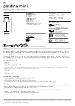
Create a cut-out (350mm x 70mm) in the mounting surface.
•
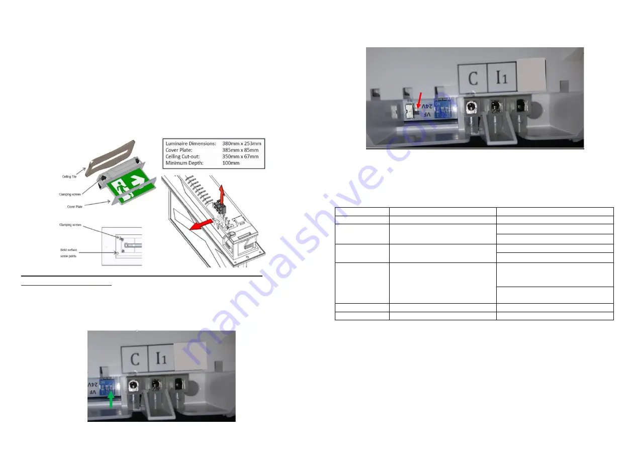
Remove the Fire Panel Input terminal block by disengaging the clip. Refer to Image below.
•
Route the power cord to the mains connection and connect the 240VAC supply.
•
Route 24/VF control cables through the access hole and connect to the terminal block as per next
step.
•
Connect positive signal of GREEN activation to
I
1
and negative signal to C (Common).
•
Reinstall the terminal block.
•
Insert the Fitting into the ceiling cavity tighten the (4) clamping screws.
•
Alternately, fix the Fitting to a solid surface using (4) screws through the surface material.
•
Install the cover plate, Apply power to the fitting and test.
•
To disable the Dynamic Green mode coming on in Emergency mode Set dipswitch 1 to OFF
position.
NOTE: For the Dip Switch setting to take effect the power and battery will need to be
disconnected and reconnected.
Dynamic Green 24 Volt (24V)/Volt Free (VF) Operation and Testing
Activation of the Dynamic Green is controlled via 24V/VF control interface. The fitting comes pre-set as
normally OFF. This is switched via an intelligent circuit inside the fitting. This is controlled by the 24V/VF
input from a fire panel or other source. If you would like to change the activation of the Dynamic Green
from Normally OFF to Normally ON change the Dip Switch no.3 on the Main LED Board found next to the
fire Panel Input terminal block.
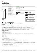
Selecting the Type of the Interface
The fitting comes pre-set to the Volt Free(VF) control interface, to change this to 24V you will have to
change the switch from VF to 24V found next to Fire Panel Input Terminal Block. Please see image
below.
Zoneworks and DATA Monitored Options
Luminaires with part numbers having -ZW
, -DATA
are fitted with Zoneworks communications modules
(nodes). These fittings are monitored using either Powerline Carrier Technology that utilises the power
cable to provide data communication or a dedicated data cable to/from data routers installed on a dedicated
data trunk connected to a central Server (can also be connected via Ethernet/Internet/Fibre). Zoneworks
software on the server is used to monitor, coordinate testing and collate test data from each fitting and can
be commissioned by scanning of the supplied barcode. The LED Test Switch indicator provides a
multifunction indication of the status of the luminaire during testing and normal operation:
Option
State
LED Operation
ZW, HV, DATA
Commissioned
LED on Solid (Green)
ZW, DATA
Un-commissioned
Batt plugged-in:
yellow 1s, green 1s
Batt unplugged:
red 1s, off 1s
HV
Un-commissioned
With network connectivity
Batt plugged-in:
yellow 1s, green 1s
Batt unplugged:
red 1s, off 1s
HV
Un-commissioned
Without network connectivity
Batt plugged-in:
yellow 250mS, green
250mS, yellow 250mS, green 250mS,
green 1s
Batt unplugged:
red 250mS, off
250mS, red 250mS,off 250mS, off 1s
ZW, DATA
Emergency Light Test In Progress
LED flashes at yellow 5s , 0ff 1s
HV
Emergency Light Test In Progress
LED flashes at yellow 1s , 0ff 1s
In the case of the DATA version a 2-
way “figure 8” cable and terminal block facilitates the connection to
the DATA network via a multi-drop bus (daisy chain connection).
Note
: Some-HV products come standard with the ability to trigger the Dynamic mode through Zoneworks
system. To check if your product has this capability look for the ZWGA logo on the Technical Label.
For further information of installation of a Zoneworks system, please refer to the Zoneworks Users Guide
and Commissioning Guide (incl. DATA version)
Warranty:
For Product Warranty information and Terms and Conditions of Sales please refer to our website
http://clevertronics.com.au/terms-conditions-sale-australia-nz