Cleveland Steel Tool 55 Ton Manual Download Page 34

30

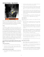
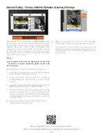
Optional Coper Notcher tooling will provide a distortion and burr 

free, three-sided shear cut to mild steel bar, plate, or angle stock 

as listed in the machine specifications as well as the capacity 

labels positioned adjacent to the Notching Station. The optional 

Coper Notcher tooling for a Cleveland Steel Tool Ironworker al-

lows for shaped, straight or angled notch cutting applications.

Setup                                                                           

Optional tooling and accessories fit within the open station of 

the machine. Optional Coper Notcher tooling is equipped with 

one, three-sided top Coper Notcher blade and three, four-sided 

bottom blades. The top blade is mounted to the moving “center” 

of the ironworker, while the bottom three blades are secured 

into a base housing. If ordered as a factory installed option, 

your Coper Notcher assembly is setup for immediate operation. 

If ordered as an option, the open cavity of the machine must 

be cleared of any existing tooling, material or debris prior to 

tooling installation. Coper Notcher blades are wearing parts 

and will need to be maintained or replaced over time. Refer to 

the maintenance section for blade maintenance, removal and 

replacement. To setup your Notching Station, observe the 

following steps:

Turn off power to machine by depressing the red stop / off 

button or lockout upstream power at the main electrical 

panel. 

Install the top Coper Notcher blade:

1.   Swing the Coper Notcher guard assembly up and away 

from the Coper Notcher table. 

2.   Install the top Coper Notcher blade with the keyway up and 

the “foot” of the blade facing the center of the machine. 

Secure the top blade using the two 3/8" socket head cap 

screws. Tighten bolts.

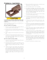
Install the Coper Notcher table:

1.   Install the Coper Notcher table assembly to the base table. 

The Coper Notcher table includes three blades secured 

within the table housing. Install with the open “U” facing 

the center of the machine. The guide foot of the top blade 

should be centered within the base table blades.

2.   Loosely secure the table from the underside of the base 

with four bolts and washers (provided). 

3.   Check for top and bottom blade alignment by powering up 

the machine and slowly inching down the top blade to meet 

the bottom blades with the foot pedal. Power the machine 

off. 

4.   Using a feeler gauge, adjust the clearance between the pe-

rimeter of the top and bottom blades to allow for .010" clear-

ance on all three sides.

5.   In the event that the top and bottom blades are not aligned, 

simply loosen the bolts under the table allowing the table to 

be moved to center the top blade within the bottom blades. 

When aligned, tighten the table bolts to secure the table.

6.   Adjust the four set screws at the sides of the Coper Notcher 

table to engage the base Coper Notcher table to the base ta-

ble. Lock the four 3/8" nuts in place to secure the set screws 

in place. These added fixtures are to provide additional sup-

port to the base table during the notching operation.

7.  Swing the Coper Notcher guard back in place. 
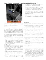
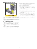
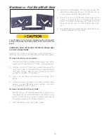
Safe Operation


Observe the following guidelines when operating the Coper 

Notcher Station.
•  Never exceed the capacities of the machine or tooling as 

described in the Ironworker specifications or listed at the tool-

ing station.

•  Check notcher blade clearance at every tooling change or 

extended operation. Maintain .010" clearance between top 

and bottom notcher blades at all times. Failure to maintain 

clearance will damage blades and support pockets.

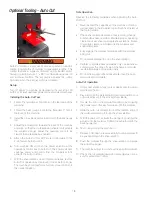
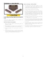
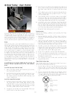
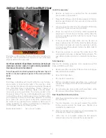
•  Cut with a minimum two of three sides of the blade surfaces 

engaging the material being notched. Cutting on one blade 

surface may overload the blades and result in tooling dam-

age or injury to the operator. See Figures A,B,C. 

•  Do not stack material to cut in the Coper Notcher station.
•  Perform complete notch operations only – partial notch cuts 

may jam the drop off side of the tooling and could result in 

breakage and operator injury.

•  Use notching aids when working with small items at the    

Coper Notcher station.

Coper Notcher Operation 


Clear the feed table of the Coper Notcher station of any tools or 

debris prior to powering the machine on.
1.  Turn machine on. The top Coper Notcher blade will be in the 

neutral position. Push the material under the tooling guard 

and into the blade area. Position your material to the desired 

cut. 

2.  Clear your hands from the working area and depress the foot 

pedal to activate the Coper Notcher station. When the cut is 

complete, release the foot pedal to automatically return the 

top Coper Notcher blade to the neutral position. 

Optional Tooling - Coper Notcher  

Figure A

Incorrect use

 - material supported 

on one blade

Figure B

Correct use

 - material supported  

by two blades

Figure C

Correct use

 - material supported  

by three blades

 Guarding removed for clarity

Summary of Contents for 55 Ton

Page 1: ...55 Ton Ironworker Manual 800 446 4402 www clevelandsteeltool com 474 E 105th St Cleveland OH 44108 Serial __________________________ ...

Page 2: ......

Page 3: ...intenance 18 Optional Tooling Auto Cut 19 Optional Accessory Light 20 Punch Station 21 Punch Operation 22 Optional Oversize Punch 23 Optional Oversize 241 Punch 24 Punch Station Maintenance 25 Punch and Die Styles 26 Optional Angle Notcher 27 Angle Notcher Maintenance 28 Optional Press Brake 29 Press Brake Maintenance 30 Optional Coper Notcher 31 Coper Notcher Maintenance 32 Optional Pipe Notcher ...

Page 4: ...tandard motor 5 HP 3 phase 208V or 230V 14amp Optional motors 5 HP 3 Phase 460V 7 amp 5 HP 3 Phase 575V 6 amp 5 HP 1 Phase 208 or 230V 23 amp Dimensions Base 44 3 8 W x 36 1 8 D x 55 1 4 H Shipping Weight 2 480 lbs Punch Station with pedestal die table 219 Punch and 413 Die Angle Shear 3 x 3 x 3 8 4 x 4 x 1 4 mild Steel Flat Bar Shear 3 8 x 14 1 2 x 12 3 4 x 4 mild Steel Fully guarded Gauge table ...

Page 5: ...The Cleveland Steel Tool Company will within one 1 year of date of purchase replace F O B the factory any goods excluding punches dies and or blades which are defective in materials and workmanship provided that the buyer returns the defective goods freight prepaid to the seller which shall be the buyer s sole and exclusive remedy for the defective goods Hydraulic and electrical components are sub...

Page 6: ...d will void your machine warranty Never leave a powered machine unattended Turn machinery OFF before walking away This machine is manufactured for use by able bodied and able minded operators only Never operate machinery when tired or under the influence of drugs or alcohol Do not resell relocate or export to a destination other than to the original point of sale Cleveland Steel Tool has designed ...

Page 7: ...l effects of occasional condensation Altitude This equipment will operate correctly up to 3 281 feet above mean sea level Transportation and Storage This equipment will withstand or has been protected against transportation and storage temperatures of 13 F to 131 F and for short periods up to 158 F It has been packaged to prevent damage from the effects of normal humidity vibration and shock Envir...

Page 8: ...al building code before installing Hertz Indication of electrical cycles per second This product should be operated only from the type of source indicated on the manufacturer s identifica tion label Installation should be in compliance with applicable sections of the National Electric Code Consult your local building code before installing Shear Crush Hazard Moving parts can cut and crush Keep han...

Page 9: ... will not be held liable for accidents caused by lack of training Wear Personal Protective Equipment To avoid physical hazard always wear personal protective equipment Wear protective eyewear clothing gloves footwear head gear and hearing protection while operating or servicing this machinery Forklift Location This machine is equipped with rated forklift move ment points Do not attempt to lift the...

Page 10: ...terminal location powering your Ironworker meets the operating specifications of the machine prior to electrical connection Confirm your electrical supply with the electrical specifications of the machine located on the Ironworker starter box It is critical that a qualified electrician install your machinery as your Warranty protection does not cover incorrect wiring of electrical components at yo...

Page 11: ...KEEPOUT Lockout power before servicing Hazardous voltage inside 7 Signal Word Panel Machine Front ...

Page 12: ...8 Signal Word Panel Machine Back Keep guards in place Hydraulic fluid is under pressure Hydraulic fluid powers moving parts FLUID INJECTION HAZARD ...

Page 13: ...9 Signal Word Panel Machine Left Machine Right Keep guards in place Moving parts can cut and crush SHEAR CRUSH HAZARD ...

Page 14: ...th a compressed air nozzle and soft cloth lighly moistened with a mild water based detergent solution Remove filings dirt dust and grime and excess lubricant from working surfaces All clean surfaces must be fully dry before powering up machine Grease all machine guides and pins supplied with a GREASE DAILY designation with NLGI Grade 2 NLGI Service GC LB or equivalent premium heavy duty lubricant ...

Page 15: ...oot Pedal Angle Shear Control Panel Grease Daily 5 Locations Flat Bar Shear Electric Stroke Control Front Cylinder Guard Operations Diagram Visit our website to view our Ironworkers in action https www clevelandsteeltool com catalog and literature videos ...

Page 16: ...e ironworker operation to shuttle between Ironworker hydraulic accessory optional or auto cut optional mode Ironworker Power the Ironworker by rotating the three position switch counter clockwise This function allows for operations of the Ironworker only Lockout Tagout This round safety red switch is set within a square safety yellow housing The switch allows for proper procedures to be followed w...

Page 17: ...ions 1 Power machine on and use the jog function of your electric foot pedal to bring tooling down to rest just above the material being worked 2 Turn machine off 3 Adjust upper handle with tapered collar to engage limit switch 4 Power machine on Tooling will stay in set position Top limit switch will be showing a red light 5 Remove material from tooling station and cycle machine Tooling should re...

Page 18: ...n the Ironworker specifications or listed at the tooling station Fully engage the material hold down with the material being cut Do not stack material to cut in the shear station Perform complete shear operations only partial shear cuts may jam the drop off side of the frame and could result in breakage and operator injury Use shearing aids when working with small items at the shear station Bar Sh...

Page 19: ...k into the blade pocket Remove and replace moving blade 1 Remove the drop off guard from the rear of the Ironwork er frame 2 Power on the machine and inch the moving center down to reveal blade bolts for the moving blade Maintenance Flat Bar Shear 3 With bolts exposed turn machine off and disconnect from power source 4 Remove blade bolts and remove blade from the blade pocket 5 With blade removed ...

Page 20: ...ng station Fully engage the material hold down with the material being cut Do not stack material to cut in the shear station Perform complete shear operations only partial shear cuts may jam the drop off side of the frame and could result in breakage and operator injury Do not shear angle smaller than the hold down will accommodate Angle Shear Operation 1 Clear shear station of any tools or debris...

Page 21: ...old down and guarding to the Ironworker frame Remove and replace moving blade 1 Remove the angle shear drop off guard from the rear of the Ironworker frame 2 Power on the machine and inch the moving center down to reveal blade bolts for the moving blade 3 With bolts exposed turn machine off and disconnect from power source 4 Remove blade bolts and remove blade from the blade pocket 5 With blade re...

Page 22: ... guidelines when operating the Auto Cut Tool Never exceed the capacities of the machine or tooling as described in the Ironworker specifications or listed at the tooling station Check shear blade clearance at every tooling change or extended shear operation Maintain proper operating clearance at bar shear and angle shear stations Failure to maintain clearance will damage shear blades and support b...

Page 23: ...vent personal injuries property damages and magnet damages 1 Neodymium magnets are brittle they can be broken or can splinter in a collision One should wear gloves and pro tective glasses when handling these magnets because splinters could disengage and fly from the magnets 2 Normal Neodymium magnets will lose their magnetic properties if heated above 175 F 80 C 3 The strong magnetic fields of neo...

Page 24: ... the wrench 6 Check for punch and die alignment by powering up the machine and inching down the punch to meet the die with the foot pedal Check to see that the punch is centered in the die 7 In the event that the punch and die are not aligned loosen the bolts under the table allowing the table to be moved to center the die When aligned tighten the table bolts to secure the table 8 Loosen bolts and...

Page 25: ... 4 and heavier 3 32 1 and over 1 8 Punching Capacities You can determine the tonnage required to punch A36 mild steel yield strength 36 300 psi 65 000 psi tensile by refer encing Figure 2 or applying the following formulas for round or shaped holes For materials other than mild steel please refer to the multiplier table 26 ga 0179 0 18 0 27 0 36 0 45 0 54 0 63 0 72 0 81 0 90 0 99 1 07 1 16 1 25 1 ...

Page 26: ...hardware provided 6 Install the oversize punch stripper assembly to the Ironworker frame with the hardware provided 7 Swing the stripper bar into place allowing for minimal clearance between the top of the material to be punched and the bottom of the stripper and tighten the stripper bar bolts Safe Operation Observe the following guidelines when operating the Oversize Punch tooling Follow manufact...

Page 27: ...at the punch is centered in the die Turn off the power to the machine 5 In the event that the punch and die are not aligned simply loosen the bolts under the table allowing the table to be moved to center the die When aligned tighten the table bolts to secure the table 6 Install and secure the 241 stripper bar to the ironworker frame allowing for minimal clearance between the top of the material t...

Page 28: ...ng a shaped die align the whistle spot with the set screw and tighten 5 Install new punch and tighten punch nut with wrench If using a shaped punch align the locating keystock of the punch with the corresponding slot within the punch stem assembly and tighten the punch nut with the wrench 6 Check for punch and die alignment by powering up the machine and inching down the punch to meet the die with...

Page 29: ... 413 1 13 16 1 1 8 419 2 3 8 1 1 4 4 3 4 28XX 1 5 32 Note Cleveland Steel Tool Ironworkers use Punch Style 228 or 241 or die Style 419 or 28XX for Oversize Hole Punching 1 4 1 8 Cleveland Steel Tool Ironworkers use 1 4 x 1 8 Keyways and Whistle Spots for alignment of shaped punches and dies Model Punch Die All Models 219 413 Punch and Die Styles ...

Page 30: ...he machine and slowly inching down the push block to meet the top blade with the foot pedal Power the machine off 4 In the event that the push block and top blade are not aligned simply loosen the bolts under the table allowing the table to be moved to center the push block centerline to the top blade When aligned tighten the table bolts to secure the table 5 Install the Angle Notcher guard with t...

Page 31: ...rews that secure the blades into the blade supports of the base table housing 2 Clean the blade pockets of any dirt or debris 3 The bottom shear blades have multiple cutting surfaces Either rotate flip the existing blade set to the new cutting surfaces or install new cutting blades into the blade pockets Re install the four 1 2 socket head cap screws and tighten The blades should be parallel to ea...

Page 32: ...achine and slowly inching down the punch to meet the bottom die with the foot pedal Power the machine off 4 In the event that the punch and die are not aligned simply loosen the bolts under the table allowing the die block to be moved to center the punch When aligned tighten the table bolts to secure the table 5 Select 1 16 3 16 1 8 or 1 4 test material for bending Rotate your four way die to your...

Page 33: ...move and replace stationary Four Way Die 1 Remove four 1 2 bolts nuts and washers from the die support brackets 2 Remove support brackets 3 Remove old die assembly 4 Place new die assembly on the Ironworker support table 5 Loosely secure the two support brackets to the support table from the underside of the base with four 1 2 bolts nuts and washers provided 6 Check for punch and die alignment by ...

Page 34: ...uge adjust the clearance between the pe rimeter of the top and bottom blades to allow for 010 clear ance on all three sides 5 In the event that the top and bottom blades are not aligned simply loosen the bolts under the table allowing the table to be moved to center the top blade within the bottom blades When aligned tighten the table bolts to secure the table 6 Adjust the four set screws at the s...

Page 35: ...de pockets of any dirt or debris 6 The bottom shear blades have multiple cutting surfaces Either rotate flip the existing blade set to the new cutting surfaces or install new cutting blades into the blade pock ets Re install the six 1 2 socket head cap screws and tighten The blades should be parallel to each other at the top surface of the working table 7 Re install the eight cap screws that secur...

Page 36: ... material into the blade area Position your material to the desired cut 3 Clear your hands from the working area and depress the foot pedal to activate the Pipe Notcher station When the cut is complete release the foot pedal to automatically return the top Pipe Notcher die to the neutral position Pipe Notcher tooling will provide a distortion and burr free notch cut to mild steel pipe and tube sto...

Page 37: ...he center down The pipe dies will close or bypass each other The push block should not come in contact with the die housing 5 Periodically lubricate the Pipe Notcher assembly as indi cated on the tooling Turn off power to machine by depressing the red stop off button and lockout upstream power at the main electrical panel Observe the following procedure when maintaining the Ironworker Pipe Notcher...

Page 38: ...work area of any tools or debris prior to powering the machine on 2 Turn the Ironworker on and insert material through the tooling guard and into the blade area Position your material for the desired cut 3 Clear your hands from the working area and depress the foot pedal to activate the tooling station 4 When the cut is complete release the foot pedal to automatically return the tooling to the neu...

Page 39: ...ris 4 Install new moving top blade to push block with allen head screws provided Re install return springs and return moving blade to base housing Remove and replace stationary blade 1 The Rod Shear or Multi Shear assembly includes one or two blades secured within the base housing Remove the six 1 2 socket head cap screws and spacers that secure the guard and blade into the base housing 2 Clean th...

Page 40: ...nd accessory controls adjacent to drop off side or end cap of the machine 3 Locate the Cleveland Steel Tool hydraulic accessory tool IMMEDIATELY ADJACENT TO IRONWORKER 4 With the Ironworker power off install the male and female accessory hydraulic hoses to the ironworker male and female quick connect hydraulic fittings Both fittings have a detent ball setting that must be aligned to couple and unc...

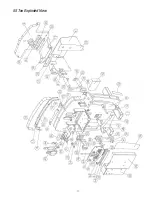
Page 41: ...37 55 Ton Exploded View ...

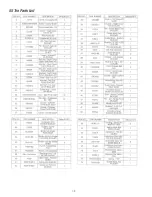
Page 42: ...38 55 Ton Parts List ...

Page 43: ...ine Check fuse at starter box Check fuse at transformer box Check for loose microswitch connections Check for damaged microswitch Distortion of small angle shear cut Check radius orientation of blade Brass shavings below gib pins and slides Brass shavings are common and expected during the break in period and after blade maintenance Hydraulics feel hot after operation Hydraulic system operates wit...

Page 44: ...40 www clevelandsteeltool com 474 E 105th St Cleveland OH 44108 800 446 4402 ...

Reviews: