


CDF MODULAR DUST COLLECTOR
Page 7
© 2017 CLEMCO INDUSTRIES CORP.
www.clemcoindustries.com
Manual No. 23478 Rev D
NOTE: Wiring schematics for the pulse-sequence panel,
exhauster motor, control panel and other electrical
accessories are included when accessories are furnished
by Clemco Industries Corp. Refer to the Project Table of
Contents for locations of the electrical wiring schematics.
2.7.1
The dust collector should be controlled by a
separate switch to enable its operation before and after
all other components in the system. Wire all other
components to start in series to prevent overloading any
component. The last segment in the system that the
abrasive reaches should start first and stop last. A
complete blast and recovery facility will have the dust
collector start first, followed by the abrasive cleaner,
bucket elevator, and floor recovery. Shutdown will be in
reverse order.
2.7.2
Electrical connections are required for the
exhauster motor and pulse-sequence control panel. Unless
the collector is operated in conjunction with a Clemco-
provided system control panel, a customer-supplied starter
is also required. When the exhaust fan is connected, make
sure it rotates in the direction of the scroll.
2.7.3
Sequence panel wiring must enter through the
bottom of the panel to avoid potential leakage.
2.8
External Grounding to Earth Ground
2.8.1
To dissipate static electricity, attach an external
grounded wire from an earth ground to the grounding lug
located next to the sequence panel.
2.9
Compressed Air Connections
NOTICE
The air source for the filter pulse must be 35 to
50 degrees Fahrenheit dew point and be free of
any oil contaminants. If line air does not meet
this requirement, an optional air dryer is
recommended. Moisture or oil contaminants in
the pulse system will decrease cartridge life
and filtering efficiency.
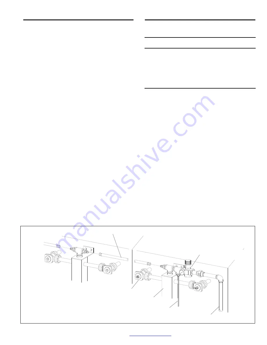
2.9.1
CDF-16 and larger dust collectors require an
Interconnecting hose, to supply compressed air between
pulse manifolds. Attach interconnecting hose(s) between
each pulse manifold as shown in Figure 4.
2.9.2
A compressed-air line must be supplied to the
pressure regulator located on the pulse-manifold inlet.
The size of the line depends on the number of modules.
The compressor and piping supplying air to the pulse
manifold must be large enough to provide at least 3 cfm
per cartridge. Purge the air-supply line to remove
moisture or other foreign material before connecting it to
the pulse manifold.
2.9.3
The air line should not be smaller in diameter
than the manifold inlet at the regulator. Note that the
connections shown in Figure 4 are typical; the actual
connections should suit the application. Install unions as
needed to enable removal of items for service or
replacement. NOTE: The regulator is located on the
pulse-manifold to safeguard against an unintentional
change of the pressure setting. If there is no chance of
unauthorized pressure changes, the regulator may be
relocated to a more accessible location.
Figure 4
Interconnecting Hose
Compressed-Air Supply
Pressure Regulator
Air tubing to differential pressure gauge
Pulse Manifold
Diaphragm Pulse Valve


