background image

P1789E   06/04

9

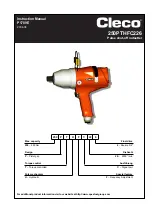
250PTHFC226

5. What to Do, If...

... the torque is too low?

- Is the exhaust air throttle adjusted correctly?
- Is the flow pressure too low?
- Is the reverse button not in one of its end positions?
- Is the inlet screen choked?
- Is the muffler choked?
- Is the oil volume in the pulse unit sufficient?

6. Repair Instructions

6.1 Disassembling the Motor

-

Clamp tool at the pistol grip <1> in a vice with plastic jaws.

Caution!

Caution!

Do not damage the rubber coat of the grip.

-

Loosen housing <92> counterclockwise using a strap wrench.

-

Pull off housing and pulse unit.

-

Remove countersunk screw <11> and reverse button <10>.

-

Remove circlip <46>.

-

Knock pistol housing against soft base and remove motor parts.

-

When the push-rod <33> is actuated, the shut-off unit can be
pulled off manually. If required, force rotor <41> from deep groove
ball bearing <36>.

6.2 Diassembling the Switch-On Valve

-

Lift push-button <21> off with size 2 screw driver.

-

Unscrew valve plug <19> with pin wrench 

<F>

 (pin spacing 11

mm, diameter 2 mm) counterclockwise.

-

Remove unscrewed valve unit downward.

6.3 Assembling the Motor

Caution!

Caution!

To prevent damaging the O-rings, apply grease to them
before assembly (Order No. 914392).

During assembly, be sure to observe the sequence
shown in the spare parts drawing.

-

Force rotor cover <37> with deep groove ball bearing <36> onto
rotor <41> using assembly device 

<E>

 (8. Assembly Notes,

fig. 1+2).

-

Slide on air distributor <35>.

-

Install seal ring <29> in shut-off piston <30>.

-

Slide push-rod <33> into rotor <41> (assembly aid) and put onto
assembly device 

<G>

 (fig. 4).

-

Install shut-off bolt <32> and balls <42>.

-

Lock compression spring <31> in bore.

-

Install pre-assembled shut-off piston <30> onto rotor.

-

Lift complete rotor, without push-rod <33> from the assembly
device. The shut-off piston is thereby locked to the rotor.

-

Install governor <28> - <22> (7. Spare Parts Drawing)

-

Insert O-ring <34> in pistol grip housing.

-

Slide the pre-assembled parts into the pistol grip housing. The
groove in the circumference of the air distributor <35> should be
aligned to the center of the switch-over groove, to allow to secure
the assembly with the pin.

-

Fasten reverse button <10> with countersunk screw <11>.

-

Slide rotor cylinder <38> with cylinder pins <39> and <40> into the
pistol grip housing.

-

To simplify assembly grease the pins <39> and <40>.

-

Push the blades <43> into the slots in the rotor <41>.

-

Install ball bearing <45> in rotor cover <44> and then assemble
both with the pistol grip housing.

-

Fit circlip <46>.

Caution!

Caution!

Do not cover the bore in the rotor cover <44>.

-

Slide push-rod <33> back into the rotor.

The motor module must be switched on only when it has
been completely assembled with pulse unit <55> and
housing <92>.

Caution!

Caution!

When installing the strainer <6>, be sure the circlip <7>
lies flat on the strainer.

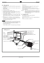
6.4 Disassembling the Pulse Unit

This is allowed only if you can guarantee filling with the oil
filler unit 

<A>

. The pulse unit must have cooled down to

room temperature.

-

Clamp hydraulic cyclinder <86> in vice with flat jaws using
assembly device 

<C2>

 (8. Assembly Notes, fig. 5)

To prevent hazard to your health and the environment, be
sure to observe the locally applicable rules for safety and
prevention of accidents.

-

Loosen bearing ring <56> with the assembly device 

<C1>

.

-

Loosen plug screw <88>.

-

Remove the pulse unit from the assembly device 

<C2>

.

-

Remove plug screw <88> and bearing ring <56> while holding the
unit above an oil pan.

-

Separate hydraulic cylinder <86> and hydraulic rotor <73> by
slightly pressing on the latter.


The hydraulic blades are spring-loaded!

-

Remove the parts installed in the hydraulic rotor by removing the
two circlips <66> and <83>.

-

Clean all parts.

Caution!

Caution!

Generally use only original CLECO spare parts. If spare
parts not manufactured by us are installed, the
manufacturer of the nutsetter is entitled to deny any
warranty claims.

6.5 Assembling the Pulse Unit

Caution!

Caution!

To prevent damaging the O-rings, apply grease to them
before assembly (Order No. 914392).

-

Assemble the pulse unit by reversing the assembly sequence
outlined for disassembly (7. Spare Parts Drawing).

-

Be sure to observe the right installation position for the two control
blades <71> and <72> (8. Assembly Notes, fig. 6 - 15).

-

To simplify assembly, use the assembly device 

<D>

.

-

Using assembly device 

<C>

 screw bearing ring <56> into the

hydraulic cylinder until stop.

-

Loosen bearing ring by 360° +90° and fill unit with oil as outlined
in section 6.6.

Summary of Contents for 250PTHFC226

Page 1: ...Pulse shut off nutsetter Instruction Manual P1789E 2004 06 250 P T H F C 22 6 Max capacity Final drive 250 250 Nm 6 Square 3 4 Design Drehzahl P Pistol grip 22 2200 1 min Torque control Ausführung T Torque controlled C Signal port Puls mechanism Special feature H Hydraulic F Frequency Adjustment ...

Page 2: ...ateur doivent être obligatoirement respectées par toute personne chargée de l installation le fonctionnement et la maintenance de l outil Sécurité Lire d abord attentivement les consignes de sécurité et le mode d emploi spécifique à ce type d outil et uniquement faire fonctionner l outil lorsque son utilisation a été parfaitement comprise Symboles Signal de danger Ce signe vous met en garde contie...

Page 3: ...onar la herramienta sin haber leído y comprendido estas instrucciones y el manual específico de este modelo Símbolos Atención Este símbolo indica un situación potencial de peligro Pueden producirse lesiones físicas a las personas si no se respeta esta advertencia Este signo indica una situación potencialdedaños Sinorespeta esta advertencia pueden producirse daños en los componentes o en las piezas...

Page 4: ...ä h f u A p i r g l a n o i t i d d a n o i s n e p s u s e l l a n n o i t i d d a è n g i o p n o i s n e p s u s e r a i l i s u a a r u t a n g u p m i o i c n a g l a n o i c p o a r u d a ñ u p m e n o i s n e p s u s f u a l r e e L d e e p s e e r f e d i v à n o i t a t o r o t o u v a à t i c o l e v o í c a v n e d a d i c o l e v n e s l u P e s l u p r e s l u p i s l u p m i o s l u ...

Page 5: ...rehzahl 1800 min nicht unterschreiten da sonst eine unruhige Leerlaufdrehzahl entstehen kann 4 Inspektion und Wartung Eine regelmäßige Inspektion ist unerlässlich um damit verbundene Betriebsstörungen hohe Reparaturkosten und lange Stillstandzeiten des Impulsschraubers zu vermeiden Bei Wartungs und Inspektionsarbeiten immer Sicherheitshinweise P1687S und die typspezifische Betriebsanleitung beacht...

Page 6: ...rteilers 35 mittig zur Umschaltnut ausgerichtet werden um ein Abstecken mit dem Stift zu ermöglichen Umschaltknopf 10 mit Senkschraube 11 montieren Rotorzylinder 38 mit Zylinderstiften 39 und 40 in Pistolen gehäuse einschieben Aus Montagegründen sind die Stifte 39 und 40 ebenfalls einzufetten Lamellen 43 in Rotorschlitze 41 stecken Kugellager 45 in Rotordeckel 44 einbauen und komplett in Pistoleng...

Page 7: ...üllen Nadelrolle 63 wieder montieren Lagerring 56 auf das geforderte Drehmoment anziehen 8 Montagehinweise Bild 16 Kugellager 90 in Gehäuse 92 einbauen O Ring 91 einle gen Impulseinheit auf Motorbaustein abtecken Ausgleichsscheibe 89 auf Hydr Zylinder 86 montieren Gehäuse 92 auf Pistolengehäuse 1 aufschrauben und mit Bandschlüssel fest anziehen Anmerkung Kleinere Blasen die bei hohem Unterdruck in...

Page 8: ...wise fluctuate 4 Inspection and Maintenance Regular inspection is essential in order to prevent breakdowns high repair costs and long downtimes associated with the pulse nutsetter Always follow and use the safety notes P1687S and this type specific operating manual for maintenance and inspection tasks The inspection and maintenance list below contains timings checks and maintenance tasks to be car...

Page 9: ...e pin Fasten reverse button 10 with countersunk screw 11 Slide rotor cylinder 38 with cylinder pins 39 and 40 into the pistol grip housing To simplify assembly grease the pins 39 and 40 Push the blades 43 into the slots in the rotor 41 Install ball bearing 45 in rotor cover 44 and then assemble both with the pistol grip housing Fit circlip 46 Caution Caution Do not cover the bore in the rotor cove...

Page 10: ...ringe B be sure there are no bubbles Reinstall needle roller 63 Tighten bearing ring 56 to the required torque 8 Assembly Notes fig 16 Install ball bearing 90 in housing 92 Insert O ring 91 Lock pulse unit to motor module Install equalizing washer 89 to hydraulic cylinder 86 Screw housing 92 onto pistol grip housing 1 and tighten it using a strap wrench Remarks Small bubbles appearing at high vacu...

Page 11: ...réparation élevés et des temps d immobilisation prolongés de la visseuse à impulsions Lors des opérations de contrôle et de maintenance toujours respec ter et appliquer les consignes de sécurité P1687S et la manuel d instructions spécifique au modèle La liste ci contre de contrôle et de maintenance indique les consignes de maintenance de contrôle et de temps pour 100 250 et 500 heures de service d...

Page 12: ...conique 11 Introduire le cylindre du rotor 38 avec les goupilles cylindriques 39 et 40 dans le carter du pistolet Pour des raisons de montage il est nécessaire de d enduire également de graisse les goupilles 39 et 40 Insérer les palettes 43 dans les fentes du rotor 41 Monter le roulement à billes 45 dans le cache du rotor 44 puis monter l ensemble dans le carter du pistolet Monter la bague de sécu...

Page 13: ...lle Monter à nouveau l axe de satellite 63 Visser la bague filetée 56 au couple de serrage requis 8 Instructions de montage figure 16 Monter le roulement à billes 90 dans le carter 92 Installer le joint torique 91 Installer l unité d impulsion sur le bloc moteur Monter la rondelle 89 sur le cylindre hydraulique 86 Visser le carter 92 sur le carter du pistolet 1 puis le serrer fermement à l aide de...

Page 14: ...tenzione Un controllo regolare è indispensabile per evitare anomalie di funzionamento elevati costi di riparazione e lunghi periodi di non utilizzo dell avvitatore ad impulsi Durante i lavori di controllo e manutenzione occorre utilizzare e osservare sempre le istruzioni per l uso specifiche e le indicazioni di sicurezza P1687S L elenco dei controlli e della manutenzione seguente contiene informaz...

Page 15: ...ità 10 con la vite a testa piatta 11 Infilare il cilindro rotore 38 con le spine cilindriche 39 e 40 nel corpo pistola Per migliore il montaggio ingrassare anche le spine 39 e 40 Infilare le palette 43 negli intagli 41 del rotore Installare il cuscinetto a sfere 45 nel coperchio rotore 44 e montare il gruppo preassemblato nel corpo pistola Installare l anello seeger 46 Importante Importante Non co...

Page 16: ...imontare la spina 63 Serrarelaghiera 56 allacoppiarichiesta Istruzionidimontaggio no 8 fig 16 Montare il cuscinetto a sfere 90 nel corpo 92 Inserire l anello ad O 91 Innestare l unità impulsi sul modulo motore Montare la rondella 89 sul cilindro idraulico 86 Avvitare il corpo 92 sul corpo pistola 1 e serrare bene utilizzando una chiave a fascetta Nota Piccole bolle all interno dello strato di inum...

Page 17: ...aciones de servicio altos costos de reparación y largos paríodos de parada del atornillador de impulsos Para los trabajos de mantenimiento e inspección acatar y emplear siempre las instrucciones de seguridad P1687S y el Manual de Instrucciones específico Lasiguientelistadeinspecciónymantenimientocontieneinstrucciones sobre tiempo control y mantenimiento para las 100 250 y las 500 horas de servicio...

Page 18: ...a varilla Montar el botón conmutador 10 con tornillo exagonal 11 Introducir el cilindro del rotor 38 con los pivotes del cilindro 39 y 40 en la carcasa de la pistola Por razones de montaje deben engrasarse también los pivotes 39 y 40 Meter las láminas 43 en la ranura del rotor 41 Montar el cojinete de bolas 45 en la tapa del rotor 44 y montar después completo en la carcasa de la pistola Montar el ...

Page 19: ...illo de aguja 63 Apretar el anillo roscado 56 al momento de apriete requerido 8 Instrucciones de montaje Fig 16 Montar el cojinete de bolas 90 en la carcasa 92 Colocar el anillo O 91 Conectar la unidad de impulso al elemento constructivo del motor Montar la arandela de compensación 89 en el cilindro hidráulico 86 Enroscar la carcasa 92 a la carcasa de la pistola 1 y aprtar bien con llave de cinta ...

Page 20: ...mbled Expédition avec outil en sac de plastique ne pas assemblé Spedizione con l utensile in sacchetto di plastica smontato Enviro con herramienta en bolsa de plástico Teil des Motor Service Kits 542868 Included in motor service kit 542868 Comprise dans le motor service kit 542868 Contenuto nel motor service kit 542868 Viene con la motor service kit 542868 siehe 10 Hinweise see 10 Notes voir 10 Re...

Page 21: ... R O g n i r o e u q i r o t t n i o j O d a o l l e n a a c i r ó t a t n u j 5 2 1 4 8 8 2 9 1 r e t l a h l e g u K t r o p p u s l l a b s e l l i b e d t r o p p u s e r e f s o t r o p p u s s a l o b a t r o p 6 2 1 3 2 3 0 9 8 l e g u K l l a b e l l i b a r e f s a l o b 7 2 5 2 7 3 3 9 1 e b i e h c s l e s s o r D r e h s a w e l t t o r h t e l l e d n o r e n o i z a t i m i l i d e t...

Page 22: ...E DE RECAMBIOS Teil des Hydraulik Service Kits 542869 Included in hydraulic service kit 542869 Comprise dans le hydraulique service kit 542869 Contenuto nel service kit idraulico 542869 Viene con la service kit hidráulica 542869 siehe 10 Hinweise see 10 Notes voir 10 Remarques vedere 10 Note ver 10 Notas ...

Page 23: ... t e l a p o l l o r t n o c i d a t t e l a p l o r t n o c e d a t e l a p 3 7 4 6 8 8 2 9 1 r o t o R r d y H r o t o r c i l u a r d y h e u q i l u a r d y h r o t o r o c i l u a r d i e r o t o r o c i l u á r d i h r o t o r 4 7 2 2 7 5 2 9 1 e b i e h c S r e h s a w e l l e d n o r a l l e d n o r a l e d n a r a 5 7 6 2 7 8 2 9 1 r e d e f k c u r D g n i r p s n o i s s e r p m o c n o...

Page 24: ... X Pressing in bearing see dimension X Enfoncer le palier voir X Piantare i cucinetti vede X Empujar el rodamiento ver X 1 X 0 00 0 02 mm 0 0000 0 0008 in X 41 36 37 E1 E2 E3 3 Rotor auspressen Rotor disassembly Démonter le rotor Smontaggio rotore Desmontaje de rotor ca 30 60N 6 7 13 5 lbf 2 y 0 01 0 02 mm 0 0004 0 0008 in 3 2 Prüfen des Axialspiels Y Checking Axial movement Y Vérifier jeu axial Y...

Page 25: ...der Impuls Einheit Dismounting of the pulse unit Démontage de l unité d impulsion Smontaggio dell untià idraulica Desmontaje de la unidad de impulso Lösen des Lagerrings 56 Loosen the bearing ring 56 Déserrage de la bague du palier 56 Svitare la ghiera filettata 56 Aflojar el anillo 56 Impuls Einheit Pulse unit Unité d impulsion Unità ad impulsi Unidad de impulso C1 C2 5 31 3x 42 41 G 30 35 36 37 ...

Page 26: ...inheit Assembly of the pulse unit Montage de l unité d impulsion Montaggio dell unità idraulica Montaje de la unidad de impulso Montage der Hydro Lamelle Assembly of the hydraulic blade Montage de la palette hydropneumatique Montaggio della paletta idraulica Montaje de la paleta hidráulica B 73 70 2 6 ...

Page 27: ...era filettata 56 Apriete del anillo 56 C2 C1 56 Anzugsmoment 340 Nm 40 Nm Tightening torque 250 lbf ft 30 lbf ft Couple de serrage Coppia di avvitatura Par de apriete 16 71 72 14 15 13 Montage der Steuer Lamelle Assembly of the control blade Montage de la lame à côntrole Montaggio della paletta di controllo Montaje de la paleta de control 62 ...

Page 28: ...o i g r e p o v i t i s o p s i d e l a i s s a l a i x a o g e u j l e d e t s u j a r o t o r l e d 1 E V 8 0 6 7 0 V m m 0 0 0 e s l ü H m m 0 0 0 e v e e l s m m 0 0 0 e l l i u o d m m 0 0 0 a l o c c o b m m 0 0 0 o t i u g n a m 2 E V 9 0 6 7 0 V m m 1 0 0 e s l ü H m m 1 0 0 e v e e l s m m 1 0 0 e l l i u o d m m 1 0 0 a l o c c o b m m 1 0 0 o t i u g n a m 3 E V 0 1 6 7 0 V m m 2 0 0 e ...

Page 29: ...bleibt Mount the circlip so that the drill hole in the rotor cover remains uncovered Monter la bague de sécurité ainsi que le forage du chapau de rotor reste découvert Montare l anello Seeger lasciando aperto il foro del coperchio rotore Montar el anillo de retención de tal manera que el agujero de la tapa del motor quede abierto Abdeckung 51 zurückstülpen und Befestigungsschraube mit Gabelschlüss...

Page 30: ...62 802 1718 Fax 425 497 0496 Fax 717 757 5063 Tel 905 501 4785 Fax 905 501 4786 Germany England France China Cooper Power Tools Cooper Power Tools Cooper Power Tools SAS Cooper China Co Ltd GmbH Co OHG a company of a company of a company of a company of Apex Tool Group LLC Apex Tool Group LLC Apex Tool Group LLC Apex Tool Group LLC Unit G Quinn Close Zone Industrielle 955 Sheng Li Road Postfach 30...

Reviews: