


Chapter 5 — Starting and Operating Instructions
Part No. 750-184
5-3
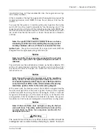
for the CB-LE, when viewed from the front of the boiler (see Figure
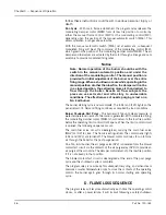
5-1). The air pump rotation is clockwise when viewed from its
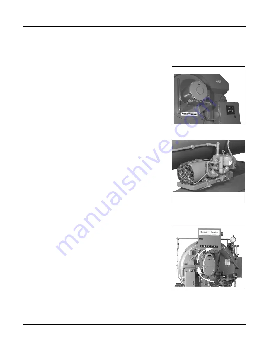
drive end. When operating a standard 60” boiler the fan motor and
air pump should rotate clockwise when viewed from the front of
the boiler (see Figure 5-3).
Before operating the boiler feed pump or oil supply pump, be sure
all valves in the line are open or properly positioned.
For safety reasons, perform a final pre-startup inspection, especially
checking for any loose or incomplete piping or wiring or any other
situations that might present a hazard.
Note: The pressure vessel support legs are welded to mounting skids in
front and secured by bolts at the rear of the pressure vessel. The
bolts are tightened for shipment. When the boiler is installed, and
prior to initial firing, the bolts securing the rear legs to the skid must
be loosened to allow for expansion and contraction caused by
differences in temperature between pressure vessel and skids and
to avoid damage to the equipment.
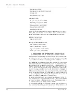
B. CONTROL SETTINGS - STEAM AND HOT WATER
See Chapter 6 for adjustment instructions for the following controls.
Inspect the
Operating Limit Control
for proper setting.
1. The operating limit pressure control of a steam boiler should be
set slightly above the highest desired steam pressure, but at
least 10% lower than the setting of the safety valve.
2. The operating limit temperature control on a hot water boiler
should be set slightly above the highest desired water tempera-
ture and within the limits of the pressure vessel.
Inspect the
High Limit Control
for proper setting.
1. On a high pressure steam boiler, the high limit pressure control
should be set approximately 10 psig above the operating limit
pressure control setting, if feasible, or midway between the oper-
ating limit pressure and the safety valve setting. The setting on a
low pressure steam boiler may be 2 or 3 psig above the operat-
ing limit setting, but must not exceed the safety valve setting.
2. On a hot water boiler, the high limit temperature control should
be 5-10
°
F above the operating limit temperature control setting
but within the limits of the design pressure of the pressure ves-
sel.
Inspect the
Modulating Control
for proper setting. The control must
be set and adjusted so that the modulating motor returns to low fire
position before the operating limit control opens. It is further
desirable to have its low point setting somewhat below the cut-in
setting of the limit control so that the burner operates in low fire
position for a brief period on each start rather than immediately
driving to a high fire position.
Figure 5-1 Fan Motor CB-LE
FAN
MOTOR
ROTATION
COUNTERCLOCKWISE
Figure 5-2
Air Compressor CB-LE
(CB Option)
AIR
COMPRESSOR
ROTATION
CLOCKWISE
FROM
DRIVE
END
Figure 5-3
Fan Motor and Air
Pump, Model CB (clockwise
rotation)
Summary of Contents for CB Ohio Special 100 HP
Page 2: ...ii ...
Page 8: ...viii ...
Page 42: ...Chapter 2 Burner Operation and Control 2 22 Part No 750 184 ...
Page 116: ...Chapter 6 Adjustment Procedures 6 28 Part No 750 184 ...
Page 126: ...Chapter 8 Inspection and Maintenance 8 6 Part No 750 184 ...
Page 153: ...Chapter 9 Parts Part No 750 184 9 3 Insulated Front Head Model CB LE ...
Page 154: ...Chapter 9 Parts 9 4 Part No 750 184 Insulated Front Head Interior Model CB LE ...
Page 155: ...Chapter 9 Parts Part No 750 184 9 5 Insulated Inner Door Model CB OS ...
Page 156: ...Chapter 9 Parts 9 6 Part No 750 184 Insulated Rear Head CB LE ...
Page 157: ...Chapter 9 Parts Part No 750 184 9 7 Insulated Rear Head CB LE ...
Page 158: ...Chapter 9 Parts 9 8 Part No 750 184 Insulated Rear Head CB OS ...
Page 159: ...Chapter 9 Parts Part No 750 184 9 9 Dry Oven Model CB LE ...
Page 161: ...Chapter 9 Parts Part No 750 184 9 11 Motor Impeller Model CB LE ...
Page 162: ...Chapter 9 Parts 9 12 Part No 750 184 Front Head Linkage ...
Page 170: ...Chapter 9 Parts 9 20 Part No 750 184 Control Cabinet Hawk ICS ...
Page 171: ...Chapter 9 Parts Part No 750 184 9 21 Control Panel Standard ...
Page 172: ...Chapter 9 Parts 9 22 Part No 750 184 Entrance Box ...
Page 173: ...Chapter 9 Parts Part No 750 184 9 23 Front Head Electrical CB LE ...
Page 174: ...Chapter 9 Parts 9 24 Part No 750 184 Front Head Electrical CB LE ...
Page 175: ...Chapter 9 Parts Part No 750 184 9 25 Front Head Electrical CB OS ...
Page 176: ...Chapter 9 Parts 9 26 Part No 750 184 Front Head Electrical CB OS ...
Page 179: ...Chapter 9 Parts Part No 750 184 9 29 Heavy Oil Piping 60 Steam CB LE ...
Page 180: ...Chapter 9 Parts 9 30 Part No 750 184 Heavy Oil Piping 60 Steam CB LE SEE TABLE NEXT PAGE ...
Page 181: ...Chapter 9 Parts Part No 750 184 9 31 Common Oil Parts Heavy Oil ...
Page 182: ...Chapter 9 Parts 9 32 Part No 750 184 Side Mounted Air Compressor Piping ...
Page 183: ...Chapter 9 Parts Part No 750 184 9 33 Air Compressor Piping CB OS ...
Page 185: ...Chapter 9 Parts Part No 750 184 9 35 Light Oil Piping ...
Page 186: ...Chapter 9 Parts 9 36 Part No 750 184 Light Oil Air Piping Front Head ...
Page 187: ...Chapter 9 Parts Part No 750 184 9 37 Light Oil Air Piping Front Head PAGE 9 31 ...
Page 191: ...Chapter 9 Parts Part No 750 184 9 41 Gas Train 125 150 HP ...
Page 193: ...Chapter 9 Parts Part No 750 184 9 43 Gas Train 200 HP ...
Page 195: ...Chapter 9 Parts Part No 750 184 9 45 Steam Pressure Controls ...
Page 196: ...Chapter 9 Parts 9 46 Part No 750 184 Hot Water Temperature Controls ...
Page 197: ...Chapter 9 Parts Part No 750 184 9 47 Water Column ...
Page 198: ...Chapter 9 Parts 9 48 Part No 750 184 Water Column ...
Page 199: ...Chapter 9 Parts Part No 750 184 9 49 Fireside Gaskets CB LE ...
Page 200: ...Chapter 9 Parts 9 50 Part No 750 184 Fireside Gaskets CB OS ...


