1.
Before operation
To assure a safe transport the units are packed to different
size boxes. Open the box and checked the containts. Make
sure that all the equipment listed below is included in the box:
●
Floor cleaning machine
●
Water discharge hose
●
Extension cable 20 metres
●
Water bucket, 12 litres
●
Pushbar
●
Tank cover
●
2 Suction hoses
●
Operation instructions
●
Safety regulations
1.1 Assembling the pushbar
☞
Dismount the screws (
A
) from
the joints of the lower pushbar.
☞
Place the joints of the upper
pushbar into the lower.
☞
Adjust the pushbar to the con-
veniant height and fix it by
pulling the two screws (
A
)
tightly.
1.2 Attaching the vacuum hoses
☞
Place cover onto the tank and fix the hoses to the
sockets on the tank cover
1.3 Electrical connection
☞
Connect the 20 metres extension cable by making a
loop in the cable and push it through the hole of the
cable tensioner. Pull the loop and place it over the
holder for the cable.
☞
Make sure that the electrical tension on the units cor-
responds to the tension in your cable socket.
☞
Connect the extension cable to the short cable of the unit.
☞
Connect the plug to the socket of the mains.
1.4 Filling with cleaning solution
☞
Fill the tank eith clen water.
☞
Add cleaning agent in the required quantity. ( Dilution
rates will be on the label of the cleaning agent )
Only use non-foaming cleaning agents that are
suggested for the cleaning of hard floors with auto
scrubbers.
For damages caused to the vacuum motor by foam
entering the manufacturer gives absolutely no warranty.
In case of foam occuring in the tank and anti foam
agent to the dirty water tank!
2. Operating
2.1 Scrubbing and vacuuming
Before cleaning, the surface must be swept.
☞
Lower the brush by turning the
lever for brush relieve (
6
).
☞
Switch-on in following order
Pumpe (
2
), Brush drive (
2a
),
Vacuum motor (
2b
).
☞
Test drive! Check if the cleaning
performance is well. If neccessary
change the dilution of the cleaning
solution.
NOTICE!
During breaks always relieve the brush by lifting it with the
lever to relieve the brush. Life expectancy of the brush will
be increased.
For small and narrow places:
☞
Switch-off (
2
) the pump switch.
☞
Manually add cleaning solution to the surface by
pulling the lever (
1
) on the right side of the pushbar.
2.2 Adding cleaning solution to the surface
☞
Turn lever to lift of squeegee (
5
) and work as mentio-
ned in 2.1. After the solution is added on the entire sur-
face lower the squeegee and vacuum the entire surface.
2.3 Monitoring
☞
To avoid damaging of the floor or the machine make
sure that the brush never rotates in dry conditions.
Alway make sure enough cleaning solution is added
to the cleaning proccess (
1
).
Empty the full waste water tank by means of the dis-
charge hose (
10
). The vacuum motor may be de-
stroyed if the waste water tank is over-filled and water
or foam enters the motor. When amptying the waste
water tank the machine must be switched-off.
2.4 Working with exteral tools
☞
Place machine with brush relieved
(
6
).
☞
Connect vacuum hose (
A
) to
socket on tank cover.
.
☞
Connect spraying hose (
B
) to the
coupling at the backside of the unit.
☞
Turn lever (
C
) next to the coupling
to the tool symbol ( vertical position ).
☞
Switch on spraying pump and
vacuum motor.
A
A
2
1
2b
2a
6
5
C
B
RA 410 E - Englisch
Preparations for working, Operation
A
B
10
Summary of Contents for RA 410 E
Page 1: ...RA 410 E Swiss Made Quality 04 2012 BA 410E 000 Englisch...
Page 7: ...RA 410 E Brush motor As at 07 07 15 Time 09 59...
Page 9: ...RA 410 E Chassis As at 07 07 15 Time 09 59...
Page 11: ...RA 410 E Front suction nozzle As at 07 07 15 Time 09 59...
Page 13: ...RA 410 E Lower pushbar 1 As at 07 07 15 Time 09 59...
Page 15: ...RA 410 E Lower pushbar 2 As at 07 07 15 Time 10 00...
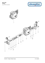
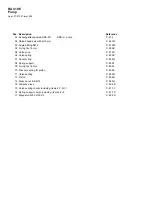
Page 17: ...RA 410 E Pump As at 07 07 15 Time 10 00...
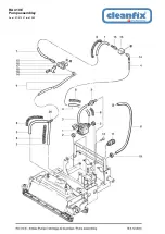
Page 19: ...RA 410 E Pump assembley As at 07 07 15 Time 10 00...
Page 21: ...RA 410 E Suction motor As at 07 07 15 Time 10 00...
Page 23: ...RA 410 E Suction nozzle As at 07 07 15 Time 10 00...
Page 25: ...RA 410 E Tank As at 07 07 15 Time 10 01...
Page 27: ...RA 410 E Wiring plan As at 07 07 15 Time 09 58...


