background image


Clavia DMI 

Service manual Nord Lead 3 rev. 1.1 

Page 2 


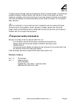
The Nord Lead 3 Service manual is arranged to help our service centers in the best way 
possible. However the Nord Lead 3 user manual is a very useful guide, use it as a 
reference in addition to this service manual. If you have access to internet you’ll find the 
user manual available for download and also a lot of useful information on our website 
www.clavia.se   
 

The information in this service manual is intended for service centers that repair 

Clavia products. It may 

not

 be copied, reposted, modified, served from other web 

pages, made into derivative works or distributed to other sources such as end users or 
retailers that do not repair Clavia products. 


h


Important safety information


Dangerous voltage levels are present within the unit.  

-  Unit should be opened exclusively by qualified service personnel. 
-  Always disconnect the power supply cord before opening to avoid  

electrical shock. 

-  Components and complete circuitboards may only be put into service when they 

are securely fixed in the instrument casing. 

Take necessary precautions against ESD before opening the unit. 


Revision history 

 
rev. 1.0 

- First release. 

rev. 1.1 

- Added pictures


- Layout changes 
- Updated Hw / Sw section, overview section 
- Added part list and error codes. 


Summary of Contents for Nord Lead 3

Page 1: ...SERVICE MANUAL...

Page 2: ...ead 3 rev 1 1 Page 1 Table of contents Overview 3 Test program 4 Running the test program 4 Error Codes 6 Hardware 7 Hardware structure 7 Opening the synth 8 Hardware configuration 9 Calibrating the D...

Page 3: ...reposted modified served from other web pages made into derivative works or distributed to other sources such as end users or retailers that do not repair Clavia products hImportant safety informatio...

Page 4: ...sound memory of Nord Lead Rack 3 consists of 8 Banks 1 8 holding 128 programs each for a total of 1024 programs plus 2 Banks 1 2 holding 128 performances each for a total of 256 performances Fuse rat...

Page 5: ...powering off the synth during a test can result in malfunction of the synth The test program may only be used by qualified service personnel and is not intended for end users In order to execute the d...

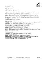
Page 6: ...o show all segments in LCD 2 Buttons Press the buttons as indicated to verify their function 3 Knobs Turn the knobs as indicated indicates turning a knob fully counter clockwise indicates turning a kn...

Page 7: ...ysEx begin message error E 2 Recv data error SysEx data message error E 3 Recv end error SysEx end message error E 4 OS erase error can t erase OS in Flash E 5 OS write error can t write OS to Flash E...

Page 8: ...21410 128k 8 bits Boot code for the host processor and test program is stored in the BootPROM U36 23690 OS user patches and performances are stored in a Flash memory U32 21290 8M 8 bits Audio D A con...

Page 9: ...Also loosen the six screws 40010 holding the MIDI jacks to the chassis Remove the 26 pole ribbon cable 22410 to the LCD board the 20 pole ribbon cable 22400 to the panel board the 10 pole ribbon cable...

Page 10: ...released main board versions However old OS versions might NOT work on newer main boards Always use the latest OS version Calibrating the DACs The Nord Lead 3 is equipped with two stereo D A converter...

Page 11: ...pdate Note To make sure you don t accidentally overwrite Sounds or performances you want to keep it s a good idea to back up the sounds For information on how to back up programs and Performances plea...

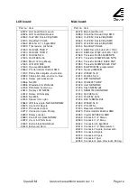
Page 12: ...di 40013 Screw AC input 40040 Screw keyboard NL3 Wood NE61 73 40025 Screw modulation wheel 40026 Screw pitch stick upper lid 40018 Screw upper lower lid 40110 Upper lid Nord Lead 3 40112 Upper lid Nor...

Page 13: ...tton black Nord ddrum 22040 Button red Nord Main board Part no Item 69073 Main board Nord 3 20980 100uF 16V 6 3x6 0 Ellyt SMD 20960 10uF 35V 5 0x6 0 Ellyt SMD 20960 10uF 35V 5 0x6 0 Ellyt SMD 20970 47...

Page 14: ...er 20730 Diod 1N5404 3A 22840 Fuse house nord dd4 mod 40076 Heatsink 23120 Drossel RN112 0 8 02 22620 Socket AC N3 NE 22480 Connector 10pol 22000 Powerswitch On off 22020 Button grey power on off 2263...

Reviews: