


CP-65 Final Testing
1. Visual Inspection
-
check the silkscreen of the chassis
-
check
scratches
-
check for all screws, washers, nuts, Pemnuts. Screws must be tight
-
check balance lock if working smoothly
-
check input/output PCB’s. Left is for Left, right is for Right.
Left PCB- R6, R7 – 33 Right PCB- R1, R2- 33
2. Electrical Test
1) check the polarities of the dc cable
2) plug-in the unit. Test and measure voltages both main and
phono Dc supply of the power supply.
3) Refer to Cp-65 Mother PCB Part 2 Electrical Test Procedure
how to measure the supply voltage of the mother PCB.
4) Readjust the bias. Offset and 200 mv on the plug-in board.
Refer to Part 2 of CP-65 Plug In Board Procedure
3. Display Test and Functions
-
refer to Cp-65 Panel and Display Procedure
4. Signal Test
1) Feed input signal 1 KHZ sinewave into input 1. Connect output
to the oscilloscope. Turn the volume up and down. Should see
both outputs. Check for noise and distortion
2) Check the unity gain of Line 1
3) Check the IR in and IR out
4) Check the 12v. trigger
5) Check balance left and right
6) Check mute on and off
7) Reset unit
8) Check back the Line 1 output. Should see output on output 1
and 2, output 1, output 2, both on balance and single ended
outputs but using the remote control
9) Check the phase
10) Repeat steps 1,2,8,9, for inputs 2,3, Tape 1, Tape 2, single
ended and balance inputs
11) Check bal. Outputs: the inverted signal should be the same
level with non-inverted signal, and should be 180 out of phase
with non inverted signal
12) Test output signals at 20 Hz, 100 Hz, 1KHz, 10 KHz, 20 KHZ
and 30 KHz square-wave. Look for noise and distortion
Summary of Contents for CP-65
Page 1: ...CP 65 Class PREAMPLIFIER SERVICE MANUAL v 1 0...
Page 2: ...Index Mechanical Assembly 3 PC Boards 17 Testing Procedures 30 Diagrams 33...
Page 3: ...CP 65 MECHANICAL ASSEMBLY...
Page 6: ...CHASSIS REAR VIEW 1 2 3 4 5 6 7 8 Class 3 CP 65...
Page 7: ...CHASSIS 1 PLA CAPFR1 2 HDW 8 FLAT WASHER 3 BZO 8 32x3 4 BHCS 4 Class 6 1 2 3 4 TOP VIEW CP 65...
Page 9: ...CP 65 PC BOARDS...
Page 10: ...MAINBOARD Class 10 CP 65 N A...
Page 11: ...CP 65 TESTING PROCEDURES...
Page 12: ...Class 14 START UP CP 65 N A...
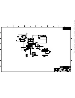
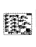
Page 13: ...CP 65 DIAGRAMS...
Page 14: ...B2BXR00 Class 16 CP 65...
Page 15: ...CP65_block sch 1 Thu Jun 20 11 11 21 2002...
Page 16: ...B2B7XR03_amp sch 1 Thu Jun 20 11 00 56 2002...
Page 17: ...B2B7XR03_amp sch 2 Thu Jun 20 11 01 28 2002...
Page 18: ...B2B6XR00_IR_input sch 1 Thu Jun 20 10 59 40 2002...
Page 19: ...B2B5XR01_Encoder sch 1 Thu Jun 20 10 59 01 2002...
Page 20: ...B2B4XR01_display_5_button sch 2 Thu Jun 20 11 07 05 2002...
Page 21: ...B2B4XR01_display_5_button sch 1 Thu Jun 20 11 08 57 2002...
Page 22: ...B2b2XR00_line input2 sch 1 Thu Jun 20 10 56 01 2002...
Page 23: ...B2B1XR02_mother_PCB_with cs3310 sch 1 Thu Jun 20 10 51 01 2002...
Page 24: ...B2B1XR02_mother_PCB_with cs3310 sch 2 Thu Jun 20 10 51 38 2002...
Page 25: ...B2B1XR02_mother_PCB_with cs3310 sch 3 Thu Jun 20 10 53 20 2002...
Page 26: ...B2B1XR02_mother_PCB_with cs3310 sch 4 Thu Jun 20 10 54 28 2002...
Page 27: ...B2B1XR02_mother_PCB_with cs3310 sch 5 Thu Jun 20 10 55 06 2002...
Page 28: ...B2B8XR02_ext ps sch 1 Thu Jun 20 11 13 08 2002...
Page 36: ......


