


10
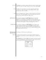
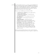
Rear Panel
The following descriptions are intended as a quick reference, should you have
any questions about your new product. Please see the next section
(entitled
Initial Setup)
for specific advice on incorporating your new amplifier into your
system.
1
Balanced (XLR) Input
Balanced audio interconnections were originally developed for the
telephone and more recently have been used in the professional audio
world for preserving the delicate nuances of extremely small microphone-
level signals. For many years now, they have also been used by
performance-oriented companies such as Classé to preserve every nuance
of the finest audio recordings in your collection.
Technically, balanced audio interconnections provide two distinct benefits:
they double the signal’s strength as it travels from one component to the
next, increasing the potential Signal-to-Noise ratio by 6 dB; they also do
an excellent job of rejecting noise and interference that might otherwise
be picked up between the components. If executed with a high degree of
symmetry between the inverting and non-inverting signal paths, balanced
connections can offer the best performance. For this reason, we strongly
recommend using the balanced analog interconnections between your
Classé components wherever possible.
The pin assignments of these
XLR input connectors
are:
Pin 1: Signal ground
Pin 2: (non-inverting)
Pin 3: Signal – (inverting)
Connector ground lug: chassis ground
These pin assignments are consistent with the standard adopted by the
Audio Engineering Society (AES14-1992).
If you are using your Classé power amplifier with a Classé preamplifier/
processor, you’re all set – just remove the supplied shorting pins (between
Pins 1 and 3) from the amplifier’s XLR connector(s), take standard
balanced interconnect cables and plug them in.
If you are using another brand of preamplifier or processor, please refer to its
operating manual to verify that the pin assignments of its output connectors
correspond to those of your amplifier. If not, have your dealer obtain cables
with the appropriate output pin connecting to the equivalent input pin.
RIGHT OUTPUT
CAUTION! TO REDUCE THE RISK OF ELECTRIC SHOCK, GROUNDING
OF THE CENTER PIN OF THIS PLUG MUST BE MAINTAINED
AVIS! POUR RÉDUIRE LE RISQUE DE CHOC ÉLECTRIQUE
LA FICHE CENTRALE DE LA PRISE DOIT ÊTRE
BRANCHÉE POUR MAINTENIR LA MISE À LA TERRE
RISQUE DE CHOC ÉLECTRIQUE-NE PAS OUVRIR
SHOCK HAZARD - DO NOT OPE N
IN
OUT
IN
OUT
CAN BUS
RS 232
UPDATE
HOST
IN
OUT
CLASS 2 WIRING
LEFT OUTPUT
LEFT INPUT
RIGHT INPUT
THIS DEVICE COMPLIES WITH PART 15 OF THE FCC RULES.
OPERATION IS SUBJECT TO THE FOLLOWING TWO CONDITIONS:
(1) THIS DEVICE MAY NOT CAUSE HARMFUL INTERFERENCE, AND
(2) THIS DEVICE MUST ACCEPT ANY INTERFERENCE RECEIVED,
INCLUDING INTERFERENCE THAT MAY CAUSE UNDESIRED OPERATION.
100-120~ T6.3AH 250V
220-240~ T3.15AH 250V
Summary of Contents for CA-D200
Page 1: ...Owner s Manual CA D200 Two Channel Amplifier ...
Page 27: ......


