background image

 OE  3004 

 DIGITAL MULTIMETER CAT. III 

OPERATING INSTRUCTIONS

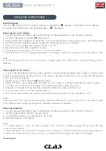
Data Hold Mode

Press the " 

H

 " button to hold the present reading on the display. "    " appears on the display as an indicator.

To exit the Data Hold mode, press the button again. "    " disappears.

Measuring DC or AC Voltage

1. Connect the black test lead to the "COM" terminal and the red test lead to the "ΩVmA°C" terminal.

2. Set the range switch to desired   


   range position.

If the magnitude of the voltage to be measured is not known beforehand, set the range switch to the highest range 

position fi rst and then reduce it range by range until satisfactory resolution is obtained.

3. Select DC or AC voltage measurement with the " AC/DC  "

button according to the marks beside this  button.

4. Connect the test leads across the source or circuit to be tested.

5. Read the display. For DC voltage measurements, the polarity of red lead connection will be indicated as  well.

Note:

To avoid damage and injury, do not measure a voltage higher than 300V de/ac although reading may be 

obtained.

Measuring DC or AC Current

1. Connect the black test lead to the "COM" terminal. Connect the red test lead to the "CVmA"C" terminal if the 

current to be measured is less than 200mA. If the current is between 200mA and 1OA, connect the red test lead 

to the "10A" terminal instead.

2. Set the  range switch to desired      range position.

3. Select DC or AC current measurement with the "AC/DC" button according to the marks beside this  button.

4. Turn off power to the circuit to be tested. Then discharge all highvoltage capacitors.

5. Break the circuit path to be tested, then connect the test leads in series with the circuit.

6. Turn on power to the circuit, then read the display.

For DC current measurements, the polarity of the red test lead connection will be indicated as  well.

Note:

If the magnitude of the current to be measured is not known beforehand, set the range switch to the highest range 

fi rst and then reduce it range by range until satisfactory resolution is obtained.

Measuring resistance

1. Connect the black test lead to the "COM" terminal and the red test lead to the "ΩVmA°C" terminal.

2. Set the range switch to desired Ω range position.

3. Connect the test leads across the abject to be  tested.

4. Read the reading on the display.

Note:

1. For measurements > 1MΩ, the meter may take a few seconds to stabilize reading. This is normal for high 

resistance measurements.

2. When the input is not connected, i.e. at open circuit, only fi gure "1" will be displayed as an overrange indication.

3. Before test, disconnect all power to the circuit to be tested and discharge all capacitors thoroughly.

Continuity test

Summary of Contents for OE 3004

Page 1: ...clas com MULTIMETRE DIGITAL CAT III DIGITAL MULTIMETER CAT III OE 3004...

Page 2: ...ant de brancher le c ble d essai sous tension Lorsque vous d branchez les c bles d essai veuillez d abord d brancher le c ble d essai sous tension Retirez les c bles d essai du multim tre avant d ouvr...

Page 3: ...ien d autres fonctions encore Cet outil de test est facile utiliser et tr s pratique Il peut par exemple s agir de mesures relev es sur les tableaux de distribution les disjoncteurs l installation lec...

Page 4: ...ble d essai rouge pour les mesures de courant 200mA 10A 7 Borne COM Cette borne est la prise de courant du c ble d essai noir Elle sert galement de prise de courant pour la borne n gative du thermoco...

Page 5: ...au format de mesure nombre de chiffres les moins significatifs TENSION CONTINUE Plage R solution Pr cision Indication de d passement de plage 200mV 100 V 0 5 5 Seul le chiffre 1 est affich l cran 2V...

Page 6: ...Pr cision Indication de d passement de plage 20mA 10 A 1 3 5 Seul le chiffre 1 est affich l cran 200mA 100 A 1 8 5 10A 10mA 3 0 5 1 Protection contre la surtension Fusible action rapide 250mA 300V po...

Page 7: ...a temp rature ambiante est stable 1 C Lorsque la temp rature ambiante varie de 5 C le degr de pr cision est effectif apr s 1 heure Plage R solution Courant d essai 1 5V La tension de fonctionnement de...

Page 8: ...pr sents c t de ce bouton 4 Coupez l alimentation du circuit tester Puis d chargez tous les condensateurs haute tension 5 Coupez le chemin du circuit tester et branchez les c bles d essai en s rie su...

Page 9: ...ne VmA C 2 Selon la tension nominale de la batterie tester r glez le s lecteur de plage sur la position BATT correspondante 3 Branchez les c bles d essai sur les deux bornes de la batterie tester 4 L...

Page 10: ...tim tre en pr sence d un champ lectromagn tique intense D tection de c bles lectriques sous tension alternative Branchez la borne d un c ble d essai sur une borne d entr e du multim tre et connectez l...

Page 11: ...rectes qui pourraient entra ner un ventuel risque d lectrocution ou de blessure corporelle veuillez remplacer la batterie d s que le voyant de batterie faible appara t Pour viter tout endommagement ou...

Page 12: ...en you disconnect test leads disconnect the live test lead first Remove the test leads from the meter before you open the battery cover or the case Do not operate the meter with the battery caver or p...

Page 13: ...detection and illumination functions are also provided lt features polarity indication data hold overage indication etc lt is easy to operate and is a very useful test tool for example stationary moto...

Page 14: ...00mA 1OA measurements 7 COM terminal This terminal is a plug in connecter for the black test lead lt is also a plug in connecter for the negative plug of the thermocouple for temperature measurements...

Page 15: ...ticant Digits DC VOLTAGE Range Resolution Accuracy Overage indication 200mV 100 V 0 5 5 Only figure 1 shown on the display 2V 1mV 0 8 5 20V 10mV 200V 100mV 300V 1V 1 0 5 1 Input lmpedance 10M Max Allo...

Page 16: ...Range Resolution Accuracy Overage indication 20mA 10 A 1 3 5 Only figure 1 shown on the display 200mA 100 A 1 8 5 10A 10mA 3 0 5 1 Overload Protection 250mA 300V FAST Fuse for VmA C terminal inputs 10...

Page 17: ...is stable to 1 C For ambient temperatures changes of 5 C rated accuracy applies after 1 hour Range Description Test current 1 5V The working voltage of the battery will be shown on the display so that...

Page 18: ...ent with the AC DC button according to the marks beside this button 4 Turn off power to the circuit to be tested Then discharge all highvoltage capacitors 5 Break the circuit path to be tested then co...

Page 19: ...lack test lead to the COM terminal and the red test lead to the VmA C terminal 2 According to the rated voltage of the battery to be tested set the range switch to the corresponding BATT range positio...

Page 20: ...n t use the meter in an environment with intense electromagnetic field Live AC Wire Detection Connect the plug of a test lead to an input terminal of the meter and connect the probe tip of this test l...

Page 21: ...which could lead to possible electric shock or personal injury replace the battery as soon as the low battery indicator appears To prevent damage or injury use only replacement fuses specified Before...

Page 22: ......

Page 23: ......
Page 24: ...icien de votre distributeur agr If you need components or parts please contact the reseller In case of problems please contact your authorized technician CLAS Equipements ZA de la CROUZA 73800 CHIGNIN...

Reviews: