
AC 5038
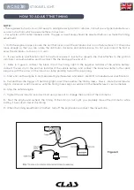
STROBE LIGHT
HOW TO ADJUST THE TIMING
NOTE :
• These general instructions will not apply to all engine designs and/or vehicles. Consult your engine manufacturer’s
service instructions which supersede these instructions.
• For vehicles with contact breaker points, the gap or dwell angle should be adjusted before you make the timing
adjustment.
1 - With the engine stopped, loosen the bolt that locks down the distributor, but do not fully remove it. It should be
loose enough so that you can rotate the distributor clockwise and anticlockwise. Do not over-loosen the bolt or
allow the distributor to move on its own.
2 - If your vehicle specifi cations and instructions require it, locate the vacuum line that attaches to the ignition
distributor vacuum advance and disconnect the line and plug the end of it.
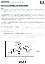
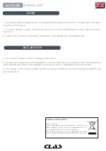
3 - Refer to Figure 3, connect the black clip of the timing light to the negative terminal of the vehicle battery,
connect the red clip to the positive terminal of the vehicle battery, and connect the inductive clamp to the spark
plug wire with the arrow on the inductive clamp painting toward the spark plug.
4 - Start and run the engine to normal operating temperature, and adjust idle RPM to manufacturer specifi cations.
5 - Pull and hold the trigger of the timing light, direct the beam at the timing marks. Slowly rotate the distributor
slightly clockwise or anticlockwise until the timing marks align, as advised in the manufacturer’s service manual.
6 - Stop the vehicle engine.
7 - Tighten the distributor lock-down bolt using care not to change the position of the distributor.
8 - Start the engine and recheck the timing. If the timing is not right, you probably moved the distributor while
bolting it back down. Reset the timing.
9 - When the timing adjustment is fi nished, turn off the engine and reconnect the vacuum line.
Figure 3