9
B. For Thicknessing
B.1 Remove the Angle Fence.
B.2 Push the Cutter Guard out of its
holder so that the Chute may be
attached to the table, as shown
in Fig.7.
Ensure both Locking keys are pushed
firmly into the slots in the table, shown
in Fig.6.
Fig. 7
1.
Set the depth of cut, using the Depth of Cut Setting Knob - see Fig.1. Turn
anticlockwise to increase the cutting depth, clockwise to decrease, using the
scale, indicated in Fig. 8, as a reference. For the initial cut, we recommend a
depth of cut of no more than 1mm. The maximum depth of cut is 2mm.
2.
Ensure the fence is at the correct angle - for normal planing, this would be 90
degrees. For other angles, use a template or angle gauge for greater accuracy.
OPERATION
A. Planing
3.
Slide the cutter guard out of the
way and place the workpiece on
the table so that it rests snugly
against the fence, with the lead
edge a short distance from the
cutter, noting that direction of
feed is right to left, looking from
the front of the machine.
4.
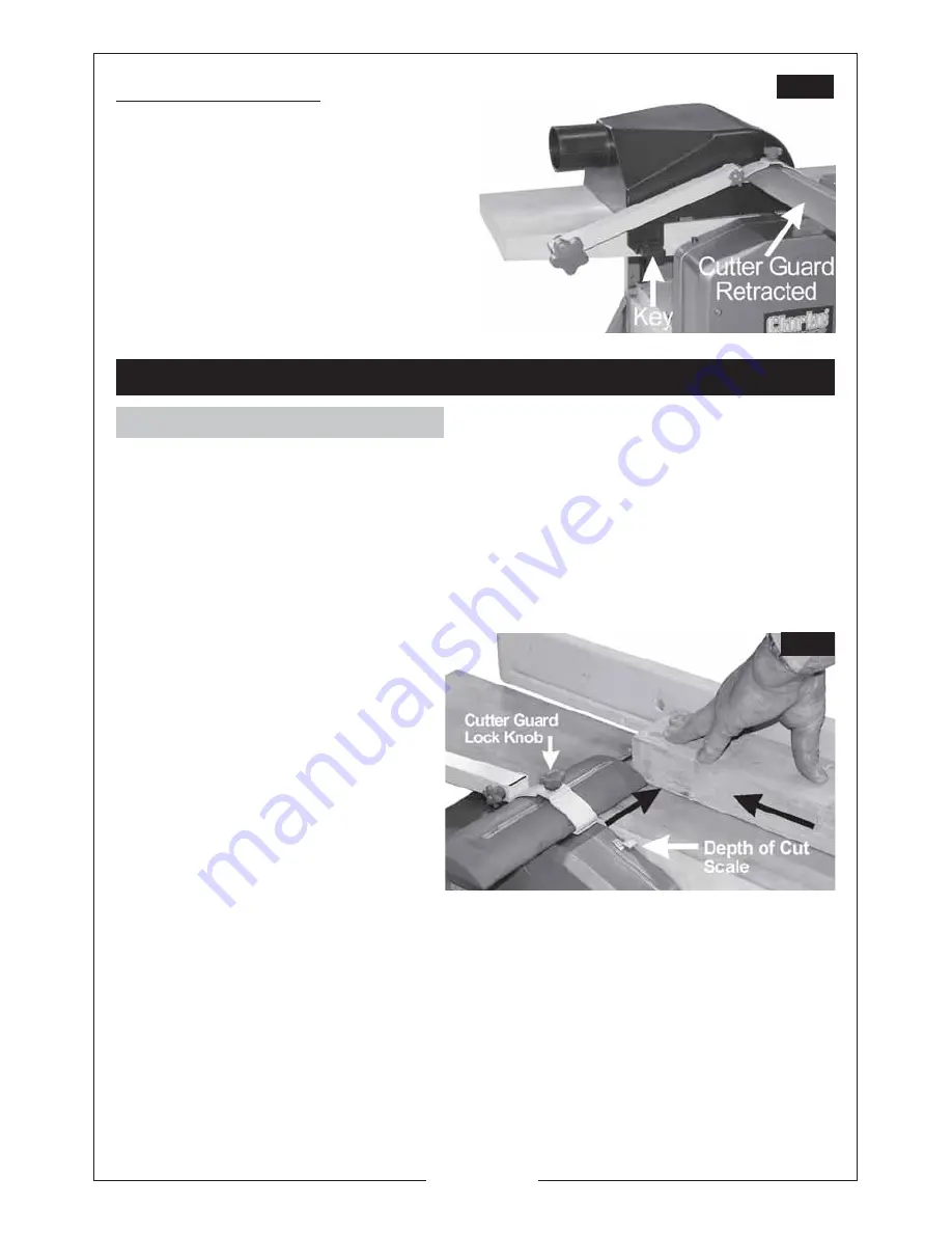
Slide the cutter guard up to lightly
touch the workpiece as shown
in Fig.8, thereby completely
covering any exposed cutter.
Fig. 8
Ensure the guard is as low as possible and the Cutter Guard Lock Knob is tightened.
5
.
Raise the cover of the ON/OFF switch and press the green ON button, marked
‘I’, and allow the machine to come up to full speed.
6.
Applying
firm
downwards pressure, and keeping the workpiece against the
fence, proceed to feed the work over the cutter. Do not feed too quickly
ENSURE the timber is completely free of nails, screws and staples etc., before use.
ALWAYS use Supports for long
pieces - Roller Stands etc.
Summary of Contents for Woodworker CPT600
Page 14: ...14 ...
Page 15: ...15 CPT600 Exploded Diagram Parts List ...
Page 16: ...16 SPARE PARTS DIAGRAM CPT600 ...
Page 19: ...19 CPT800 Exploded Diagram Parts List ...
Page 20: ...20 SPARE PARTS DIAGRAM CPT800 ...
Page 24: ...24 ...


