Clarke Woodworker CMS251 Operating & Maintenance Manual Download Page 16

ADJUSTMENTS

  Ref: Fig 16

It may be necessary from time to time, to check various settings and make
appropriate adjustments.

a. Squareness of Blade

It is most important to check that the blade is exactly perpendicular to the table.
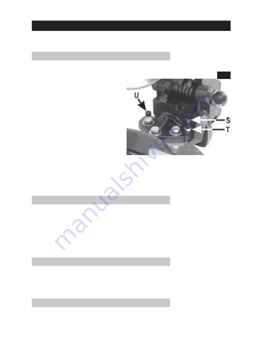
To do this, place a small square on
the table and bring it up to the
blade, checking to see if it is square.
If an adjustment is required, first
slacken the Bevel Locking Knob,
then slacken off the adjuster locknut
T, screw the adjuster (S) in or out, as
the case may be until the blade is
exactly square, keeping light
pressure on the head to keep it in
contact with the adjuster screw.
When completely satisfied, lock the
adjuster with the lock nut, and with
the head resting against the stop,
tighten the Bevel Locking Knob.

NOTE: It simplifies matters if assistance is used during this process.

Check the position of the pointer in relation to the scale. If necessary zero the
pointer by slackening off the pointer securing screw, moving the pointer
accordingly and retighten the securing screw.

b. 45

O

 Bevel Stop

Slacken off the Bevel Locking Knob, and tilt the Head to its maximum. Lower the
Blade and with a small 45

O

 gauge between the bed and blade, check for

trueness of angle.

If an adjustment is required, slacken the locknut which secures the adjuster
shown at U in Fig.16. and is found beneath the table. Turn the adjuster in or out
as the case may be, using an appropriate Hex. wrench, to acquire the correct
angle. When satisfied, lock the adjuster with the locknut.

c. Squareness of Backfence

Place a square flat on the table with its base resting on the Backfence. If it is not
square with the edge of the slot in the table, slacken off the two backfence
securing screws R, Fig.2, using an appropriate Hex. wrench, sufficient to be able
to move the fence until it is square. When satisfied, tighten the securing screws.

d. Cutting Head Spring Tension

To increase the Cutting Head spring tension, screw the adjuster (O, Fig.2), ‘IN’
using an appropriate Hex. wrench, until the required tension is achieved.

Fig.16

16

Summary of Contents for Woodworker CMS251

Page 1: ...COMPOUND MITRE SAW Model CMS251 OPERATION MAINTENANCE INSTRUCTIONS 0801...

Page 2: ...Copyright Clarke International All rights reserved August 2001 2...

Page 3: ...of of purchase This guarantee is invalid if the product is found to have been abused or tampered with in any way or not used for the purpose for which it was intended Faulty goods should be returned t...

Page 4: ...our own shadow 4 CHECK for DAMAGE before using the machine Any damaged part such as a guard etc should be checked to ensure that it will operate properly and perform its intended function Check for al...

Page 5: ...CONDITION Keep tools sharp and clean for the best and safest performance Follow maintenance instructions 21 DON T OVERREACH Keep your proper footing and balance at all times For best footing wear rubb...

Page 6: ...d from the supply 9 DO NOT operate the machine with the guards removed They must all be in place and securely fastened when performing any operation 10 Use ONLY approved replacement saw blades Contact...

Page 7: ...d with a plug which is moulded onto the electric cable i e non rewirable please note 1 The plug must be thrown away if it is cut from the electric cable There is a danger of electric shock if it is su...

Page 8: ...PRINCIPAL PARTS OF THE SAW Fig 1 Fig 2 8...

Page 9: ...awdust The extraction device may be used continuously or intermittently depending upon your requirements The Cutting Head is locked in its lower position for transit purposes To release it pull out th...

Page 10: ...lywood with a thickness of 5 8 minimum If this method is preferred the plywood support should be clamped to a solid base or workbench whenever the saw is being used 3 The Work Clamp may be slipped int...

Page 11: ...orce the blade a light pressure is all that is required You will notice that to provide maximum safety the blade is not exposed at any time and the guard rises automatically as the blade is lowered Ne...

Page 12: ...etightening the Bevel Locking Knob The 45O adjuster is factory set so that when the Head is tilted to its fullest extent the blade will cut 45O bevel The procedure for cutting is the same as that for...

Page 13: ...your CLARKE dealer for advice 2 Changing the Saw Blade IMPORTANT Exercise extreme care when handling the saw blade The tips are extremely sharp and careless handling could result in severe personal in...

Page 14: ...avoid damaging your hand on the saw blade teeth IMPORTANT The securing screw has a LEFT HAND THREAD i e turn it CLOCKWISE to undo Hints and Tips 1 When replacing the upper plastic blade guard para 4 a...

Page 15: ...in Fig 14 The cable is located on a plastic peg shown in Fig 15 and will simply pull away as you remove the brush 4 Replace in reverse order To locate the brush carrier which houses the brush correctl...

Page 16: ...ackening off the pointer securing screw moving the pointer accordingly and retighten the securing screw b 45O Bevel Stop Slacken off the Bevel Locking Knob and tilt the Head to its maximum Lower the B...

Page 17: ...Number 6500768 ACCESSORIES Replacement Saw Blades Tungsten Carbide Tipped 24 Tooth 6490110 40 Tooth 6490120 60 Tooth 6490130 Please note that the details and specifications contained herein are corre...

Page 18: ...ad TMCCMS25141 42 Sleeve TMCCMS25142 43 Spring TMCCMS25143 44 Arm TMCCMS25144 45 Bolt TMCCMS25145 46 Link Arm TMCCMS25146 47 M6 square neck screw TMCCMS25147 48 Spring Retaining Cover TMCCMS25148 49 B...

Page 19: ...19 PARTS DIAGRAM...

Reviews: