1
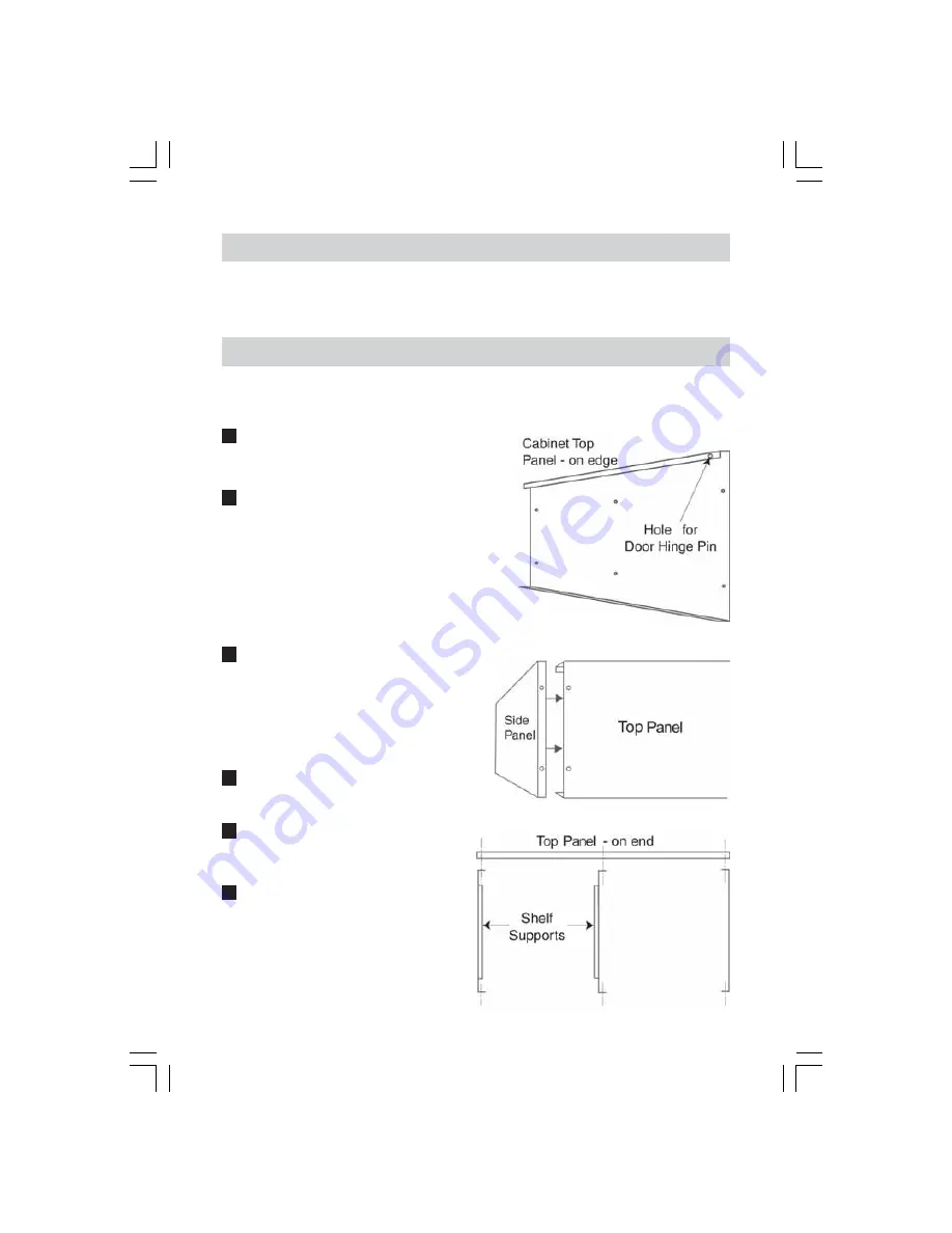
Hold the top panel (2), on its edge so that the
blind hole on the inside edge, at one end, which
is used to locate the cupboard door swivel pin,
is uppermost, facing you and to the right. FIG.1
2
Ensuring the panels are correctly oriented
attach the two side panels, (3 & 4) and the
centre panel, (5), using the screws, nuts and
washers provided. FIGS .2 & 3.
Remember - DO NOT tighten the nuts fully.
NOTE: The shelf supports attached to the end
and centre panels should be facing each other,
on the left side of the structure. FIG.3
The structure should now be resting on its side
with the three panels facing you.
Pre-Assembly check.
Unpack the components and lay out carefully. Referring to the parts list, ensure that all parts
are present. If there are any deficiencies, immediately contact the dealer from where the
product was purchased, or the Clarke International Parts Department on, 020 8988 7400.
Assembly is quite straightforward and requires the use of a screwdriver and a 10mm spanner
3
Attach the bottom panel in the same
manner as in ‘1’ above, i.e. by holding it
on its edge with the blind hole on the inside
edge uppermost. FIG.4.
Get an assistant to hold the door so that
as the back panel is offered up, the swivel
pins are entered in the two blind holes in
the top and bottom panels. FIG.4
4
Turn the structure so that it rests on its front...i.e.
the door, and attach the back panel (7).
REMEMBER - DO NOT tighten the nuts fully.
5
Whilst in this position, attach two legs, one
to each corner, then turn the structure so
that it rests on its back once again and
attach the two front legs. FIG5
6
Turn the complete assembly on to its feet
and rock it gently in order to align all
parts and to ensure that no particular
part is under stress. Ensure also that the
legs are vertical and particularly, that
the door is perfectly square in its recess.
When completely satisfied, tighten all
nuts and screws so far assembled.
FIG.1
Assembly
Note: When assembling, all screw heads should be on the outside of the cabinet.
IMPORTANT: DO NOT tighten any nuts until the cabinet is fully assembled.
The numbers in brackets refer to the item number on back page
FIG.2
On its Edge
Back
Front
FIG.3


