Clarke CBS7MB Operating & Maintenance Instructions Download Page 14

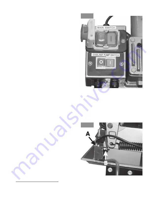
When the Arm reaches the bottom of
its travel, a bracket, attached to the
Arm and carrying an adjuster, shown at
‘B’ Fig.15, activates a microswitch, ‘A’
switching Off the machine. ALWAYS
ensure the adjuster is set so that the
microswitch operates correctly.

  ‘Running In’ the Blade

To gain the maximum working life from your blade it is also essential for a new
blade to be ‘RUN IN’ for a short period of time. This is done by applying a lighter
cutting pressure on the first few cuts made by the blade. As a guide the ‘Running
In’ cutting pressure should be half the normal cutting pressure. The cut will therefore
take longer to complete.

14

To switch OFF press the RED button
marked ‘O’,

NOTE: If this is the first time you have
operated your machine, or if a new
blade has been installed, allow the
blade to run completely off load for a
few minutes to allow the blade to settle.

With the blade running at full speed,
turn the Lever ‘B’Fig 3a, to the 6 o’clock
position again, then gently turn knob ‘A’

anticlockwise

 so that the blade slowly

lowers at the desired rate, until it
contacts the workpiece and cutting
begins.  Remember, do not start to cut
on a sharp edge.

At this point, switch ON the coolant
pump by pressing the GREEN button
marked ‘I’ (see Fig.14).

The rate of descent of the Arm determines the cutting rate and is therefore
controlled by the knob ‘A’, Fig 3a.

The cutting rate is dependant upon two main factors.......the type of material and
the thickness of cut, (which may not be constant). It therefore becomes a matter of
‘feel’.  Ideally, blade pressure should be not so light so that it simply ‘rubs’ the work,
and not so heavy as to cause the blade to wander off line or ‘grab’ the work.

Fig. 14

Fig. 15

Summary of Contents for CBS7MB

Page 1: ...7in Metal Cutting Bandsaw 7in Metal Cutting Bandsaw Model CBS7MB 0514 Part Number 6460122 Operating Maintenance Instructions...

Page 2: ...ONFORMITY Wedeclarethatthisproductcomplieswiththefollowingstandards directives 98 37 EC Product Description Metal Cutting Bandsaw Model No CBS7MB Serial Batch No See machines Data Plate signed Service...

Page 3: ...way or not used for the purpose for which it is intended The reason for return must be clearly stated This guarantee does not affect your statutory rights Contents Specifications 2 Declaration of Con...

Page 4: ...alified technician before operating ALWAYS make workshop childproof with padlocks master switches or by removing starter keys ALWAYS keep children and visitors away All children and visitors should be...

Page 5: ...material being cut ALWAYS keep your hands and fingers clear of the blade when sawing ALWAYS set the blade guide guard assembly as close as possible to the workpiece ALWAYS switch off the saw and make...

Page 6: ...D Connect BLUE coloured cord to plug terminal marked with a letter N or coloured BLACK IMPORTANT If this appliance is fitted with a plug which is moulded on to the electric cable i e non re wireable p...

Page 7: ...F Coolant Pump Switch C Motor D Pulley Cover E Gearbox F Blade Tensioner G Blade Guides H Blade Guide Carrier Lock Knob I Vise Jaw J Band Saw Tracking Adjuster K Vise Jaw Adjuster L Work Stop M Hydrau...

Page 8: ...ng an appropriate tool remove the blocks then lower on to its wheels It will now be easier to manoeuvre to your desired location Clean rust protected surfaces with kerosene paraffin or a mild solvent...

Page 9: ...al being cut The workpiece is held in a Vice which may be swivelled to provide accurate angle cutting and a work stop provides for stock pieces of equal length to be cut without having to measure each...

Page 10: ...guides which support the blade whilst cutting It is VITAL that these guides are correctly adjusted A Tensioning the Saw Blade Turn the Blade Tension Adjusting Knob arrowed in Fig 6 clockwise to increa...

Page 11: ...t the blade is supported as close to the workpiece as possible and also to ensure that any area of the blade which is not used for cutting is covered Figs 7 8 show the Moveable Guide Carriers at their...

Page 12: ...ctric motor via a drive belt and a pulley system shown in Fig 10 Four steps are provided and by positioning the belt according to the chart below four saw band speeds may be selected The chart is dupl...

Page 13: ...ockwise the adjuster bolt until the drive belt is slack enough to be repositioned on the appropriate pulleys 4 Re tension the belt by screwing IN clockwise the adjuster bolt A until one side of the be...

Page 14: ...if a new blade has been installed allow the blade to run completely off load for a few minutes to allow the blade to settle With the blade running at full speed turn the Lever B Fig 3a to the 6 o clo...

Page 15: ...se in order to lower the idler pulley This will remove all tension from the blade allowing it to be pulled from MAINTENANCE WARNING This machine MUST be disconnected from the mains supply whenever car...

Page 16: ...justment is correct It is also IMPORTANT to ensure that the blade runs in the right plane with relation to the bed and therefore the workpiece i e at right angles to the bed The two adjustments just d...

Page 17: ...is adjustment is carried out at the factory and it should not normally require readjustment If the blade is thrown first try a new blade as this should normally cure the problem If the new blade does...

Page 18: ...handle adjacent to the blade adjuster and lift the arm with the gauge or scale The gauge or scale should register no more than 5 6kg ONLY If necessary adjust the tension on the balance spring using th...

Page 19: ...ubrication 4 Idler wheel needs lubrication Excessive Blade Breakage Permanent Blade Dulling Blade Cuts Crooked Blade Cuts Rough Unusual Wear on Side Back of Blade Teeth breaking from blade MotorOverhe...

Page 20: ...5 Switch Box 1 QB7MB045 46 Coolant Pump Sw 1 QB7MB046 47 Cover 1 QB7MB047 48 Round Hd Screw 2 QB7MB048 49 NVR Switch 1 QB7MB049 50 Wire Retainer 1 QB7MB050 51 Coolant Pan 1 QB7MB051 52 Filter 1 QB7MB0...

Page 21: ...ew 2 QB7MB148 149 Adj Bkt rear 1 QB7MB149 150 Hex Nut 4 QB7MB150 151 Spring Washer 4 QB7MB151 152 Bearing 2 QB7MB152 153 Blade Adj rear 1 QB7MB153 154 Pin 2 QB7MB154 155 Washer 1 QB7MB155 156 Hex Skt...

Page 22: ...Spare Parts Diagram 22...

Page 23: ...your nearest dealer or CLARKE International as follows PARTS SERVICE TEL 020 8988 7400 PARTS SERVICE FAX 020 8558 3622 or e mail as follows PARTS Parts clarkeinternational com SERVICE Service clarkein...

Page 24: ......

Reviews: