background image

6

Parts & Service: 020 8988 7400 / E-mail: [email protected] or [email protected]

COMPRESSED AIR REQUIREMENTS

• Use only clean, dry, regulated compressed air as a power source.

• Air compressors used with the tool must comply with the appropriate 

European Community Safety Directives.

• A build-up of moisture or oil in the air compressor will accelerate 

wear and corrosion in the tool. ensure any moisture is drained from 
the compressor daily and the inlet filter is kept clean.

• If an unusually long air hose is required, (over 8 metres), the line 

pressure or the hose inside diameter may need to be increased.

• The air hose must be rated at least 150% of the maximum operating 

pressure of the tool.

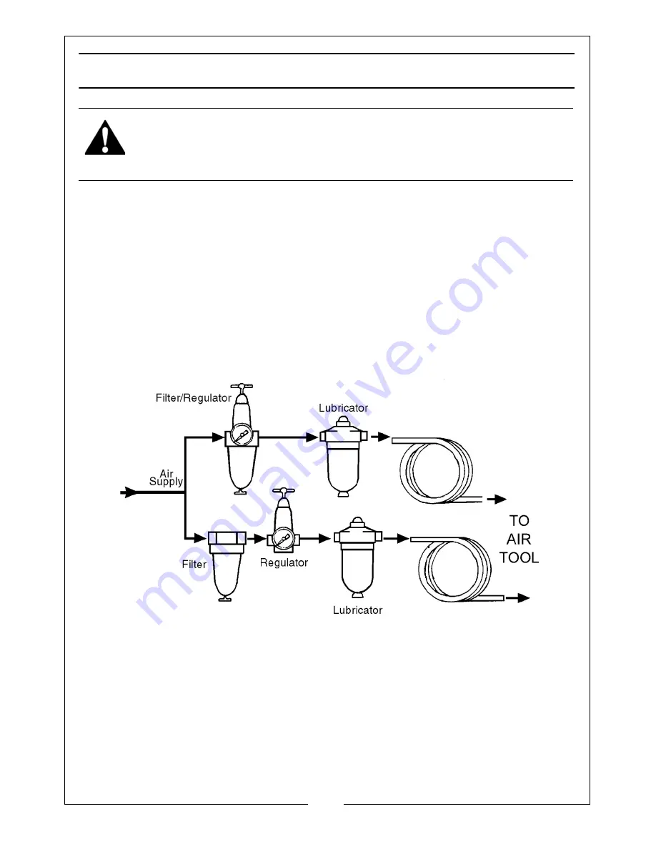
• A typical air line layout is shown above. If an automatic in-line filter/

regulator is used, it will keep the tool in good condition, but should 
be regularly checked and topped up with oil. SAE 10 oil should be 
used, and the lubricator adjusted to approx 2 drops per minute.

• Never exceed the maximum operating pressure for the tool. It is 

recommended that air pressure to this tool does not exceed 90 psi 
at the tool when running. Higher pressures and unclean air will 
shorten the life of the tool due to faster wear and is a possible safety 
hazard.

WARNING: COMPRESSED AIR CAN BE DANGEROUS. ENSURE THAT YOU 
ARE FAMILIAR WITH ALL PRECAUTIONS RELATING TO THE USE OF 
COMPRESSORS AND COMPRESSED AIR SUPPLY.

Summary of Contents for CAT130

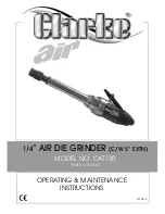
Page 1: ...OPERATING MAINTENANCE INSTRUCTIONS GC0414 1 4 AIR DIE GRINDER C W 5 EXTN MODEL NO CAT130 PART NO 3120144...

Page 2: ...carefully you encounter problems take the unit to your local CLARKE dealer IMPORTANT Please read all of the safety and operating instructions carefully before using this product The following safety...

Page 3: ...r protectors when using the air tool 4 Do not overreach Keep proper footing and balance at all times 5 Never use oxygen CO2 combustible gases or any type of bottled gas as a source of power for the to...

Page 4: ...tool They add weight and could fail due to vibration 19 Do not force or misuse the tool It will do a better and safer job at the rate for which it was designed 20 Do not remove any labels Damaged lab...

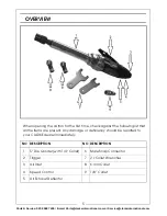
Page 5: ...rst time check against the following list that all the items are present Any damage or deficiency should be reported to your CLARKE dealer immediately NO DESCRIPTION NO DESCRIPTION 1 5 Die Grinder wit...

Page 6: ...ed to be increased The air hose must be rated at least 150 of the maximum operating pressure of the tool A typical air line layout is shown above If an automatic in line filter regulator is used it wi...

Page 7: ...ed run a few drops of oil through the tool before use It can be entered through the inlet strainer or via the hose at the nearest connection to the air supply 4 Connect a suitable hose to the air inle...

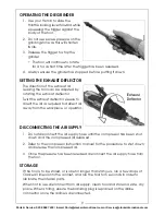
Page 8: ...new collet and screw the cap loosely back on FITTING THE GRINDING STONE IMPORTANT Never use chipped or cracked grindstones 1 Slip the shank of the chosen stone into the collet and tighten the screw ca...

Page 9: ...lector Twist the exhaust deflector sleeve to direct the air as required to deflect air away from the workpiece or operator DISCONNECTING THE AIR SUPPLY 1 Do not disconnect the air supply hose until th...

Page 10: ...fore using Tool runs slowly Air flows weakly from exhaust 1 Motor parts jammed with gum dirt 2 Regulator in closed position 3 General airflow blocked by dirt 1 Examine inlet air filter for cleanliness...

Page 11: ...r and flushing out the tool with gum solvent or oil or failing this the motor may require dismantling This is better left to your Clarke dealer SERVICE AND REPAIR If the tool runs erratically or becom...

Page 12: ...te that the details and specifications contained herein are correct at the time of going to print However CLARKE International reserve the right to change specifications at any time without prior noti...

Page 13: ...13 Parts Service 020 8988 7400 E mail Parts clarkeinternational com or Service clarkeinternational com PARTS LIST DIAGRAM...

Page 14: ...Soft Grip 32 Rotor Collar 8 O Ring 33 Front Plate 9 O Ring 34 Pin 10 Valve Stem 35 Front Rotor Bearing 11 Valve Spring 36 Sealing Ring 12 O Ring 37 Fixing Ring 13 Valve Plug 38 Chrome Nut 14 Regulato...

Page 15: ...15 Parts Service 020 8988 7400 E mail Parts clarkeinternational com or Service clarkeinternational com DECLARATION OF CONFORMITY...

Page 16: ......

Reviews: