background image

Page 10

Clarke

®


 American Sanders

 Super 7R Operator's Manual


MAINTENANCE

CAUTION:

Maintenance and repairs performed by

unauthorized personnel could result in

damage or injury.  Maintenance and

repairs performed by unauthorized

personnel will void your warranty.

Failure to perform maintenance at

recommended intervals may void

warranty.

Carbon Brushes

Inspect all four brushes every 6 months or 250 hours.

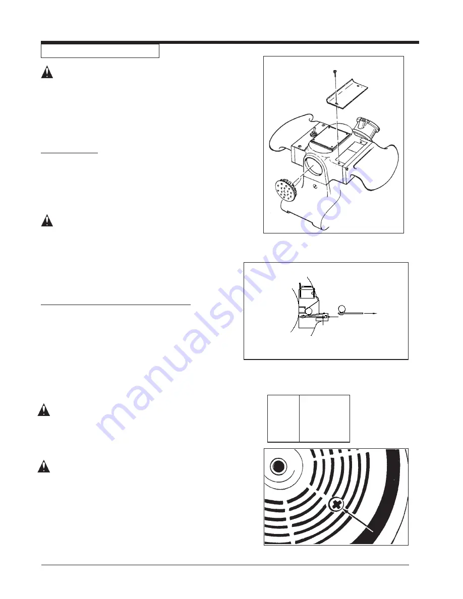
Access to the brushes is gained through the front and

back motor vent plugs and under both motor covers (figure

6).  Press tab on spring clip assembly in, rotate, then

remove (figure 7).Use needlenose pliers to disconnect the

shunt wire.  If any brush has worn to 3/8" in length or

shorter, replace the entire set.

 CAUTION:

Use only motor brush PN 40818A or

PN 40055A with shunt wire or motor

failure will occur.

When replacing the brushes make sure that the brush

seats against the commutator, the spring rest in the

recess of the brush, and the brush is free to travel.  When

returning the switch cover, keep any wires clear of the

commutator and any pinch site.

To Change The Lubricant In The Gearbox

To change the lubricant in the gearbox, follow this proce-

dure:

1. Put the machine upside down on a bench.

2. Align one of the two holes in the rubber pad with one

of the three holes in the rotating wall guard.

3. Align both holes with one of the three screws in the

gear housing cover.  Remove the screw from the gear

housing cover.  (Figure 8)

4. Align the holes with each of the other two screws,

then remove screws.

  CAUTION:

Make sure no dust enters the gear box.

Damage will occur to the gear box.

5. Remove the cover from the gear housing.

6. Remove  the old lubricant from the gearbox.

7.Add six ounces of American SandersTechnology

lubricant to the gear box.

  CAUTION:

To prevent damage to the motor, do not

add more than six ounces of lubricant to

the gearbox.

8. Using the three screws removed above, install the

cover on the gear housing.

9. Start the machine and let it run for 15 minutes.  A

small amount of excess lubricant should flow out the

vent hole.  If none appears it may be necessary to

add additional lubricant.

 10. Wipe off excess lubricant and clear vent hole.

Figure 8

Qty

Part No.

1Qt.

16610A

1Gal.

16611A

Lubricants

Figure 6

Figure 7

Summary of Contents for American Sanders 07011A

Page 1: ...gan 48906 Fax 517 484 9836 Email CustServe Michco com Web site www Michco Com Parts Web site www FloorMachineParts Com Order Parts on Line at www FloorMachineParts Com Directly to Parts Service By Email Shop Michco com By Fax 517 702 2041 By Voice Use numbers above Serving the Cleaning Industry Since 1922 Notice All copyrighted material remains property of original owners all trademarks are proper...

Page 2: ...tothemachine or to other property could occur as well You must have training in the operation of this machine before using it If you cannot read English have this manual explained fully before attempting to operate this machine Si Ud no pueden leer el Inglés se hagan explicar este manual completamente antes de tratar el manejo o servicio de esta máquina All directions given in this book are as see...

Page 3: ...s 3 Machine Specifications 5 Sanding Cuts and Sandpaper 6 MachineSet Up 7 OperatingInstructions 7 AdjustmentProcedures 8 RoutineMaintenance 8 CarbonBrushes 8 Dust Bag 8 Bearings 8 Parts and Service Manual Section II Maintenance 10 Wiring Diagram 11 AssemblyDrawing 12 Assembly Parts List 13 Contents of this Book ...

Page 4: ...d to Cigarette lighters pilot lights and any other source of ignition can create an explosion when active during a sanding session All sources of ignition should be extinguished or removed entirely if possible from the work area Work areas that are poorly ventilated can create an explosive environment when certain combustible materials are in the atmosphere i e solvents thinners alcohol fuels cert...

Page 5: ...t all labels decals warnings cautions and instructions are fastened to the machine Get new labels from your authorized Clarke American Sanders distributor WARNING Sanding dust can be airborne and can be breathed in while operating a sander Always wear a dust mask while operating sanding equipment WARNING Injury to the eyes and or body can occur if protective clothing and or equipment is not worn w...

Page 6: ... Disc 7 x 7 8 Dia Disc 7 x 7 8 Dia Disc 7 x 7 8 Dia Disc DiscRate 2800RPM 2800RPM 2800RPM 2800RPM DiscDriverSystem GearDriven GearDriven GearDriven GearDriven Power Cable 14 3GrayRubber 14 3GrayRubber 14 3GrayRubber 14 3GrayRubber DustCollection Standard Standard Standard Standard Dust Control Rate 110CFM 110CFM 110CFM 110CFM Model Super 7R Specifications Dust Collection Bag Control Switch Work Li...

Page 7: ...of finish SANDING CUTS AND SANDPAPER Initial Cut The purpose of the initial cut is to remove old finish and gross imperfections on the floor surface A coarse abrasiveshouldbeused If glazing loading or burning takes place immediately into an initial cut select a coarser abrasive If this should occur during an initial cut the abrasive has dulled and must be replaced Final Cuts The purpose of a finis...

Page 8: ...ry could occur if power is applied to the machine with the power switch already in the ON position Always check to assure that the power switch is in the OFF position before applying power to the power cable 2 Make sure the control switch is in the Off position then connect the supply cable to an appropriately grounded fused circuit Connect the supply cable to the motor pigtail Figure 4 3 With the...

Page 9: ...Using a similar tool loosen locknut B with a counter clockwise motion Figure 5 Condition Pad creates ridges on both edges or a hop is experienced Rotate both adjusting screws equal amounts clockwise Tighten locknuts and test on a piece of ply wood Repeat procedure until condition is corrected We recommend you not exceed 1 8 rotation for each attempt Condition Pad creates a ridge on the tip of the ...

Page 10: ...Clarke American Sanders Super 7R Operator s Manual Page 9 Division of Super 7R Edger Section II Parts and Service Manual 78155C ...

Page 11: ...clear of the commutator and any pinch site To Change The Lubricant In The Gearbox To change the lubricant in the gearbox follow this proce dure 1 Put the machine upside down on a bench 2 Align one of the two holes in the rubber pad with one of the three holes in the rotating wall guard 3 Align both holes with one of the three screws in the gear housing cover Remove the screw from the gear housing ...

Page 12: ...Clarke American Sanders Super 7R Operator s Manual Page 11 Model Super 7R Edger Wiring Diagram 1 03 ...

Page 13: ... 35 36 7 7 8 46 49 9 89 38 10 50 11 39 47 18 15 16 17 51 52 20 33 21 22 23 24 25 26 27 28 29 30 82 94 83 84 81 92 91 78 90 77 75 76 75 33 74 73 53 57 56 58 50 62 61 64 65 66 67 68 87 100 69 70 65 71 65 72 47 60 79 63 80 32 31 29 19 93 48 Super 7R Edger Drawing 1 03 38 98 85 99 97 96 95 65 ...

Page 14: ...s parts 64 65 70 71 72 NI Not illustrated Ref Part No Description Qty 53 42234A Cord Supply 115V 1 42182A Cord Supply 240V 1 40007A Cord Supply w AUI 10P 1 54 50952A Bag Dust 1 56 50732A Bearing 1 57 69621A Support Bag 1 58 21108A Bracket Exhaust 1 59 293406 Gasket Exhaust Bracket 1 60 302101 Clamp Wrench 1 61 962987 Screw 10 24 x 3 8 Pn St Typ 1 62 987300 Wrench 1 63 962289 Screw 20 x 3 4 Soc St ...

Page 15: ...Page 14 Clarke American Sanders Super 7R Operator s Manual NOTES ...

Page 16: ......

Page 17: ...A Nilfisk Advance Brand 14600 21st Avenue North Plymouth MN 55447 3408 www clarkeus com Phone 800 253 0367 Fax 800 825 2753 2010 Nilfisk Advance Inc ...

Reviews: