background image

13

Parts & Service: 020 8988 7400 / E-mail: [email protected] or [email protected]

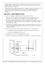
The grinding stone will wear down with use and may well go out of true. Use a 
dressing wheel or stone grader to correct the trueness and to remove worn, 
glazed grains from the stone.

The stone will have a finite life expectancy, dependant upon the nature of the 
work being done. Periodically, make a note of the wheel diameter and 
replace your (150mm) dia wheel if it reduces to an little as (130mm) in 
diameter.

INSTALLING A NEW GRINDING WHEEL

To renew or change the grinding wheels, proceed as follows

1. Switch off and un-plug from power supply. Remove the grinding wheel 

covers by unscrewing the nuts securing the three retaining screws. 

2. Remove the spark arrester bracket and eye shield by unscrewing the single 

mounting screw. Slacken the tool rest mounting bolts, and pull the bracket 
away from the wheel.

3. Hold the sanding belt roller firmly to stop the shaft rotating and remove the 

nut and flange holding the grinding wheel, remembering that the nut has a 
LEFT HAND THREAD.

4. Remove the used wheel and replace with a new one, ensuring that:

• The paper blotters and flanges are in place either side of the wheel.

• You do not overtighten the wheel nut.

5. Re-adjust the tool rest and spark arrester brackets.

6. Switch the machine on and allow it to rotate freely for at least one minute.

Summary of Contents for 6500032

Page 1: ...OPERATING MAINTENANCE INSTRUCTIONS ORIGINAL INSTRUCTIONS GC0820 rev 3 BENCH GRINDER WITH SANDING BELT MODEL NO CBG6SB PART NO 6500032...

Page 2: ...or not used for the purpose for which it was intended Faulty goods should be returned to their place of purchase no product can be returned to us without prior permission This guarantee does not effec...

Page 3: ...ower tools that have the switch on invites accidents 3 Do not overreach Keep proper footing and balance at all times This enables better control of the power tool in unexpected situations 4 Dress prop...

Page 4: ...ons to operate the power tool Power tools are dangerous in the hands of untrained users 12 Maintain power tools Check for misalignment or binding of moving parts breakage of parts and any other condit...

Page 5: ...essories must be within the capacity rating of the power tool The correct size accessories can be correctly guarded and controlled 3 Never use a stone that is chipped cracked or damaged Fragments from...

Page 6: ...damage is found 5 Always use the tool rests to steady the workpiece the torque of the spinning grinding wheel may pull the workpiece from your hands 6 ALWAYS check for damaged parts Before further use...

Page 7: ...ould cause an electrical hazard If the colours of the wires in the power cable of this product do not correspond with the markings on the terminals of your plug proceed as follows The Blue wire must b...

Page 8: ...he Clarke dealer where you purchased the product Position the machine in good light and fixed to a suitable workbench using the boltholes in the machine base No Description No Description 1 Grinding W...

Page 9: ...d and adjusted 3 Ensure that the bench grinder is mounted securely to a suitable stable work surface using the four bolt holes provided in the base We recommend that your Clarke Bench Grinder is secur...

Page 10: ...of metal that is thinner than the gap between the tool rest and the grinding wheel 1 6 mm USING THE SANDING BELT 1 Position the sander work rest as required see fig 4 and adjust as described on page 1...

Page 11: ...TTING THE EYE SHIELD AND SPARK ARRESTER Slacken the spark arrestor securing screw and position the arrester so that the recess is adjacent to the wheel with a clearance of approximately 1 6 mm as show...

Page 12: ...r which could result in damage to the wheel SETTING THE SANDER WORK REST Slacken the knob that secures the work rest in place and position the rest so that it is adjacent to the belt edge and at 90 de...

Page 13: ...follows 1 Switch off and un plug from power supply Remove the grinding wheel covers by unscrewing the nuts securing the three retaining screws 2 Remove the spark arrester bracket and eye shield by un...

Page 14: ...ing straight and true If not it will require dressing before use 2 Stand to the side of the stone and hold the dresser handle firmly Place the dresser on the tool support so that its wheels can move f...

Page 15: ...lst screwing the Tracking Adjustment screw in or out to ensure the belt runs centrally on the rollers Turn the screw anticlockwise to move the belt outwards towards the outer cover or clockwise to mov...

Page 16: ...16 Parts Service 020 8988 7400 E mail Parts clarkeinternational com or Service clarkeinternational com COMPONENT PARTS DIAGRAM...

Page 17: ...B041 12 Bolt HT6SB012 42 Spring Washer HT6SB042 13 Washer HT6SB013 43 Cable Clamp HT6SB043 14 Eyeshield HT6SB014 44 N A N A 15 Spring Washer HT6SB015 45 Cable Sleeve HT6SB045 16 Nut HT6SB016 46 Nut HT...

Page 18: ...6 66 Washer HT6SB066 77 Spring Washer HT6SB077 67 Square Neck Screw HT6SB067 78 Washer HT6SB078 68 Screw HT6SB068 79 Tool Rest HT6SB079 69 Spring Washer HT6SB069 80 Drive Roller HT6SB080 70 Belt Suppo...

Page 19: ...19 Parts Service 020 8988 7400 E mail Parts clarkeinternational com or Service clarkeinternational com DECLARATION OF CONFORMITY...

Page 20: ......

Reviews: