Clarke 6012200 Operating & Maintenance Instructions Download Page 18

18

3. An appropriate current must then be set by turning the Welding Current Selector

located on the front panel o the machine. With practice you will gain a feel for the

correct current setting for different welding rod thicknesses.
The size (diameter) of welding rod should be approximately the same as the

thickness of metal to be welded.
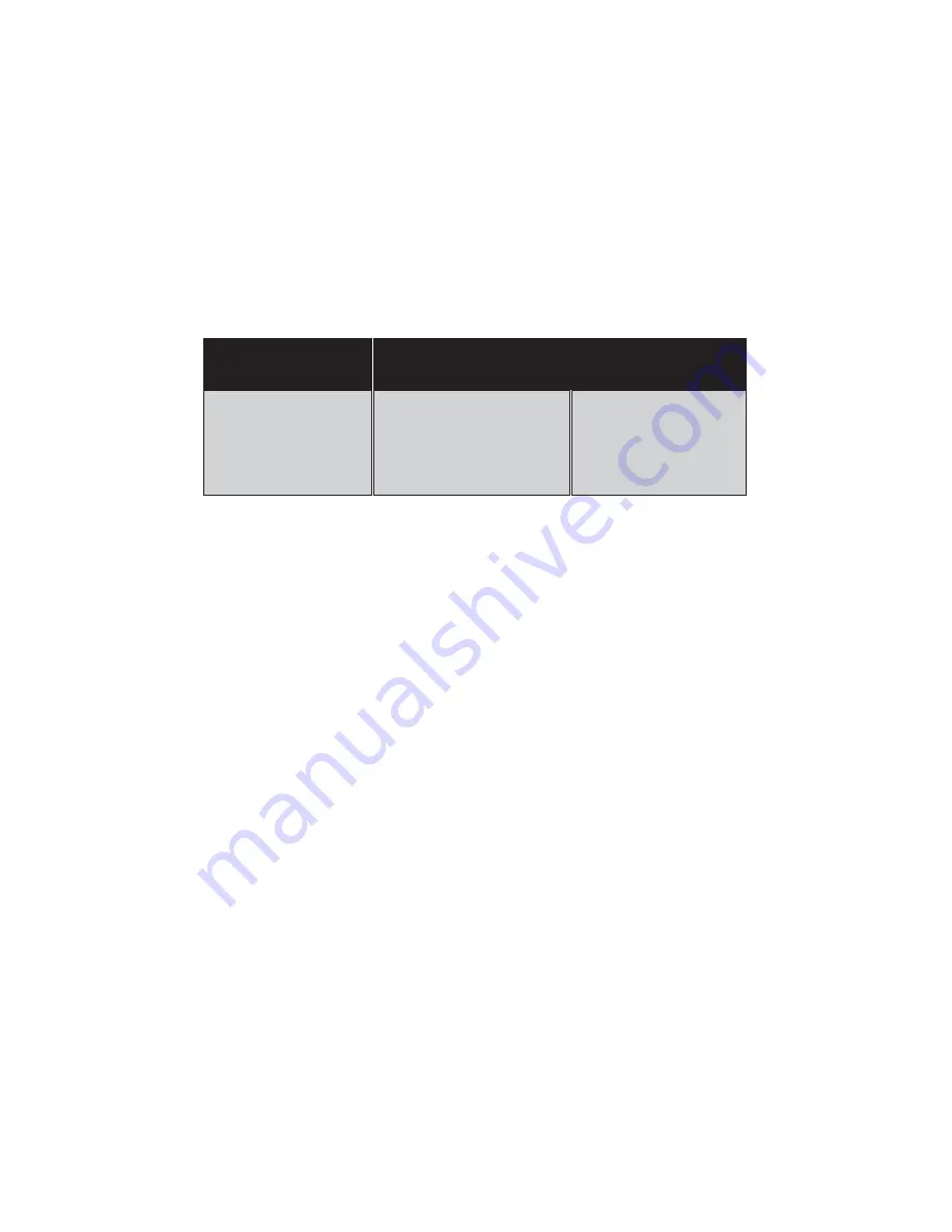
For beginners, the following table gives some useful guidelines.

SIZE OF

THICKNESS

CURRENT

WELDING ROD

OF WORKPIECE

SETTING (AMPS)

1.5mm

16  SWG - 1.5 MM.

30 - 40

2.0mm

14  SWG - 2.0 MM.

50 - 65

2.5mm

12  SWG - 2.5 MM.

70 - 100

3.0mm

10  SWG - 3.25MM

100 - 130

4.

Switch ON using the switch located on the rear panel. The green light on the

front panel should glow, indicating the machine is ON.

Note: If the machine stops at any time and the amber light comes ON the
thermal overload has intervened

5. The most difficult aspect of the arc welding process, particularly for  beginners,

is that of striking an arc.  We strongly recommend that you practice on some

pieces of scrap metal to get the feel of the operation, before you start on an

actual welding job.

6. Hold the electrode about 10mm. from the work and at an angle of about

70

°

 to 80

°

 to the work surface; take care not to accidentally touch the workpiece

until you are ready to commence.

7. Holding the welding mask close-up to the face, give a short stroke with the

electrode on the workpiece.  As soon as the arc is primed, withdraw the

electrode from the workpiece to leave a tiny gap of around 1.5mm (1/16").

The current will flow across the gap with a crackling noise and brilliant arc.

Continue to weld in one direction, maintaining the small gap as you go.  At
the end of the run just withdraw the electrode fully from the workpiece.

Note:  When you prime the arc be sure to withdraw the electrode fairly swiftly

to leave the 1.5mm. gap, otherwise the electrode will weld itself  to the

workpiece. Should this occur give the electrode a short sharp jerk to free it

and, if necessary prime the arc again. If you cannot free the electrode, switch
the machine off immediately, and free it off.

8. Inspect the job carefully.  With a correct combination of rod size and current

setting, the area of the weld should be a complete fusion of the electrode

metal with the metals being joined.  Slag forming on the surface should be

chipped away with a chipping hammer or pick. ALWAYS wear your safety
goggles when chipping away slag.

Summary of Contents for 6012200

Page 1: ...ARC TIG INVERTERS Arc Tig85 Arc Tig110 Arc Tig155 ARC TIG INVERTERS OPERATING MAINTENANCE INSTRUCTIONS 0708...

Page 2: ...th cable For Spare Parts and Service please contact your nearest dealer or CLARKE International on one of the following numbers PARTS SERVICE TEL 020 8988 7400 PARTS SERVICE FAX 020 8558 3622 or e mai...

Page 3: ...d if the product is found to have been abused or tampered with in any way or not used for the purpose for which it was intended Faulty goods should be returned to their place of purchase no product ca...

Page 4: ...REA Before installing welding equipment the user shall make an assessment of potential electromagnetic problems in the surrounding area Avoid using your inverter in the vicinity of a other supply cabl...

Page 5: ...evel 2 4 Equipotential bonding Bonding of all metallic components in the welding installation and adjacent to it should be considered However metallic components bonded to the work piece will increase...

Page 6: ...A hard hat should be worn when others work overhead Flammable hair preparations should not be used by persons intending to weld or cut B Toxic fume prevention Severe discomfort illness or death can r...

Page 7: ...suitable fire extinguishing equipment during and for some time after welding or cutting if a appreciable combustibles including building construction are within 10m b appreciable combustibles are furt...

Page 8: ...sparks 2 Eye and head protection Protect eyes from exposure to arc NEVER look at an electric arc without protection Welding helmet or shield containing a filter plate shade no 12 or denser must be us...

Page 9: ...welding gouging or spot welding operations 2F TO PROTECT AGAINST SHOCK Keep body and clothing dry Never work in damp area without adequate insulation against electrical shock Stay on a dry duckboard...

Page 10: ...so equipped the electrode wire becomes electrically LIVE when the power source switch is ON and welding gun switch is closed Never touch the electrode wire or any conducting object in contact with th...

Page 11: ...s are unobstructed Welding arc can seriously damage your eyes Both operator and spectators must ALWAYS use a proper welding face shield or helmet with suitable filter lenses Proper gloves and working...

Page 12: ...th input connections greater than 10M in length NEVER point the TIG torch at any person or animal NEVER touch the TIG torch nozzle until the welder is switched OFF and the nozzle has been allowed to c...

Page 13: ...rc stream into the molten weld pool In this manner filler metal is deposited as the electrode is progressively consumed The arc is moved over the work at an appropriate arc length and travel speed mel...

Page 14: ...process is ideally suited for welding thin metals pressure vessels heat exchangers pipes etc where accuracy and a high quality weld is desired as it produces a very low porosity weld TIG Welding Proce...

Page 15: ...rd 13 Amp plug MUST NOT be used with these welders c BOTH MODELS IMPORTANT The wires in the mains lead are coloured in accordance with the following code Green Yellow Earth Blue Neutral Brown Live As...

Page 16: ...4 AMBER LED will illuminate when the thermal overload has cut in Item 5 ve positive lead socket Item 6 ve negative leads socket Arc TIG 85 110 a GREEN LED ON Power ON OFF Power OFF Also indicates tha...

Page 17: ...or undervoltage The unit will continue to check the line voltage and automatically reset once the acceptable voltage is detected A ARC WELDING Refer to Fig 1 An Arc welding kit is supplied with this m...

Page 18: ...ode about 10mm from the work and at an angle of about 70 to 80 to the work surface take care not to accidentally touch the workpiece until you are ready to commence 7 Holding the welding mask close up...

Page 19: ...are the unit for TIG welding it is important that you adopt the following procedure 1 Plug the work return lead earth clamp in to the ve terminal and secure the work clamp tothe workpiece For good con...

Page 20: ...kpiece it is advisable to strike the arc in the joint where the mark will be concealed by the weld b Thin sheet and stainless steel may be welded with or without filler similar to gas welding The fill...

Page 21: ...han the guidelines shown below Under normal working conditions removing the covers and cleaning with dry compressed air at reduced pressure once a year will be quite sufficient Cleaning at more freque...

Page 22: ...0 Dark glass 82x108 art 471 bs din11 Hammer brush Electrode holder 200A Welding cable 16 mm2 m 3 cl 200 dn25 Dinse plug 25sqmm cx20 Earth clamp art 261 ok 150 200A Earth cable 16 qmm mt 2 TIG155 1 EM2...

Page 23: ...PARTS DIAGRAM ARC TIG 85 110 23...

Page 24: ...PARTS DIAGRAM ARC TIG155 24...

Page 25: ...25 WIRING DIAGRAM ARC TIG155 ARC TIG 85 110...

Page 26: ...lue of the supply voltage nc Symbol for the number of reference electrodes capable of being melted with the welding power source starting from the cold state without operation of the thermal cut out I...

Page 27: ...5Amps 35 140Amps 60 50Amps 60Amps 105Amps 100 40Amps 45Amps 75Amps eg With an Arc TIG 110 machine you may weld at 60 Amps for 6 minutes 60 in a 10 min cycle or continuously at 45Amps Please note that...

Page 28: ......

Reviews: