background image

7

NEVER 

stand on the log splitter.

• Serious injury could occur if the machine tips over. 

DO NOT

 store anything above or near the log splitter where a person 

might stand on the log splitter to reach it.

AVOID INJURY FROM AN UNEXPECTED ACCIDENT

DO NOT

 straddle or reach across the splitting area when operating the 

log splitter. 

NEVER

 pile logs to be split in a manner that will cause you to reach 

across the log splitter. 

• Only use your hands to operate the control levers. Never use your foot, 

knee, a rope, or any other extension device. 

ALWAYS

 pay full attention to the movement of the wedge ram. 

NEVER

 attempt to load your log splitter while the ram is in motion. 

• Keep hands out of the way of all moving parts. 

NEVER

 try to split two logs on top of each other. One of them may fly up 

and hit you.

PROTECT YOUR HANDS

• When the ram of the log splitter is in the return mode, keep your hands 

off the machine – the log splitter is designed to automatically stop when 
the cylinder is fully retracted.

• Keep your hands away from splits and cracks which open in the log. 

They may close suddenly and crush or amputate your hands/fingers. 

DO NOT

 remove jammed logs with you hands.

DON'T FORCE THE TOOL

• It will do a better and safer job at its design rate.

DO NOT 

use log splitter for a purpose for which it was not intended.

DO NOT

, under any circumstances, alter your log splitter. This equipment 

was designed and engineered to be used in accordance with the 
operating instructions. Altering the equipment or using the equipment in 
such a way as to circumvent its design capabilities and capacities, 
could result in serious or fatal injury and will void the warranty.

NEVER

 try to split logs larger than those indicated in the specifications 

table on page 2. This is dangerous and may damage the machine.

NEVER LEAVE LOG SPLITTER RUNNING UNATTENDED

DO NOT

 leave log splitter until it has come to a complete stop

Summary of Contents for 3402041

Page 1: ...OPERATION MAINTENANCE INSTRUCTIONS ORIGINAL INSTRUCTIONS DL1221 PETROL DRIVEN LOG SPLITTER MODEL NO LOGBUSTER P8 PART NO 3402041...

Page 2: ...TIONS CAUTION CAREFULLY READ THROUGH THIS ENTIRE OPERATOR S MANUAL BEFORE USING YOUR NEW LOG SPLITTER TAKE SPECIAL CARE TO HEED THE CAUTIONS AND WARNINGS Engine Power 196cc 6 5Hp Operating Temperature...

Page 3: ...se in the rain Wear protective gloves Danger Keep clear of moving parts Wear eye protection Do not remove jammed logs with your hands Wear hearing protection Before starting any repair maintenance or...

Page 4: ...ating log splitters may result in serious personal injury 2 Use safety equipment ALWAYS wear eye and ear protection Safety equipment such as non skid safety shoes close fitting clothing and suitable w...

Page 5: ...RSTAND YOUR LOG SPLITTER Read and understand the owner s manual and labels affixed to the log splitter Learn its limitations as well as the specific potential hazards AVOID DANGEROUS WORKING CONDITION...

Page 6: ...S DO NOT smoke or have open flames when operating or refilling the log splitter with oil or petrol NEVER operate the log splitter near a flame or spark Oil and petrol are highly flammable KEEP BYSTAND...

Page 7: ...is in the return mode keep your hands off the machine the log splitter is designed to automatically stop when the cylinder is fully retracted Keep your hands away from splits and cracks which open in...

Page 8: ...erformance Control levers and the power switch must be kept clean dry and free from oil and grease at all times PROTECT THE ENVIRONMENT Take any used oil to an authorized collection point DO NOT disch...

Page 9: ...ve is on the outside of the wheel assembly 2 Secure the wheel using the circlip supplied 3 Repeat with the other wheel to the other end of the axle rod and secure with the remaining circlip 4 Place th...

Page 10: ...SHER 1 Move Pusher back towards the steel stud 2 Lift Pusher a little or move left or right to align the holes on the Pusher with the screws on the steel stud 3 Tighten the two M8 nuts onto the two sc...

Page 11: ...e the hole on the lever matches the hole on the valve seat 2 Fit the control lever into position using the M8 Hex bolt and washer supplied as shown The bolt should pass through the hole on the valve s...

Page 12: ...two M10 Hex bolts supplied as shown 2 Fix the wood catcher to the work table using 4 x M8x30 bolts M8 washers and nuts 3 Fix the wood supporting frame using 8 x M10x25 bolts M10 washers and nuts Fix...

Page 13: ...to the work table as shown using 2 x M8x20 bolts M8 washers and nuts 5 Fix the small guard using 2 x M6x16 bolts M6 washers and nuts as shown On the opposite side fix the big guard using 3 x M6x16 bo...

Page 14: ...the engine oil levels using the orange capped oil dipstick If the oil level is below 2 grooves from the bottom of the dipstick see diagram on page 15 then top up the engine oil using SAE10W 30 engine...

Page 15: ...GINE START STOP STARTING THE ENGINE 1 Open the gas petrol valve by moving it to the right 2 Close the choke by moving it to the left NOTE If the engine is already hot it is not necessary to close the...

Page 16: ...gine starts move the choke to 1 2 choke position 7 After 15 seconds open the choke by slowly moving it to the right NOTE Moving the choke too fast can stall the engine 8 Adjust the throttle to the spe...

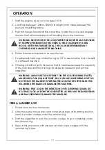
Page 17: ...r moves back and completely stops at its starting position insert a wooden wedge under the jammed log 3 Start the logsplitter to push the wooden wedge to go completely under the jammed log 4 Repeat th...

Page 18: ...stick and place it back into the oil tank remove the dipstick and make sure the oil level is between the 2 grooves on the dipstick 6 Replace dipstick making sure it is tightened to avoid leakage NOTE...

Page 19: ...ducts PROBLEM CAUSE REMEDY When the control levers are pushed down but the pusher does move Oil level is too low Check and fill up oil level Ram Pusher won t retract Oil level is too low Check and fil...

Page 20: ...20 COMPONENT PARTS...

Page 21: ...o Description 1 Oil Filter 19 Wood Supporting Frame Left 2 Oil Level Indicator 20 Wood Supporting Frame Right 3 Return Oil Pipe 21 Wood Protection Guard 4 High Pressure Oil Pipe C 22 Operating Handle...

Page 22: ...22 DECLARATION OF CONFORMITY...

Page 23: ...chainsaws with up to 20 bars PVC coated inside for easy cleaning Part No 3402095 Reduces friction to extend life of the blade Suitable for pressure pump fed chainsaws Part No 3050865 Chainsaw Log Hors...

Page 24: ......

Reviews: