background image

4

Parts & Service: 020 8988 7400 / E-mail: [email protected] or [email protected]

7. Do not fit the tool to any stand or clamping device that may damage it.

8. Do not carry out any alterations or modifications to the tool.

9. Always disconnect from the air supply when:

• Performing any maintenance.

• The tool is not in use.

• The tool will be left unattended.

• Moving to another work area.

• Passing the tool to another person.

10. Never use the tool if it is defective or operating abnormally.

11. The tool should be serviced at regular intervals by qualified service 

personnel.

12. Avoid damaging the tool by applying excessive force of any kind.

13. Always maintain the tool with care. Keep it clean for the best and safest 

performance.

14. Quick change couplings should not be located at the tool. They add 

weight and could fail due to vibration.

15. Do not force or misuse the tool. It will do a better and safer job at the rate 

for which it was designed.

16. Do not remove any labels. Damaged labels should be replaced.

17. This tool vibrates with use. Vibration may be harmful to your hands or arms. 

Stop using the tool if discomfort, a tingling feeling or pain occurs. Seek 
medical advice before resuming use.

USE OF THE GRINDING TOOLS

1. Try to hold the tool with both hands. Ensure that the workpiece is kept at 

waist height where possible. Never use the tool between the legs whilst 
sitting on the floor.

2. Ensure that sparks and particles resulting from use do not create a hazard, 

Use screens where appropriate.

3. Never bump the grinding stones onto the workpiece, or let it hit any other 

objects while grinding.

4. Always allow the tool to run up to full operating speed before applying it to 

the job.

5. Use clamps, or vices to hold the workpiece. Failure to secure the workpiece 

could result in personal injury.

Summary of Contents for 3120193

Page 1: ...OPERATING MAINTENANCE INSTRUCTIONS ORIGINAL INSTRUCTIONS GC0418 ISS 1 MULTI SANDER KIT MODEL NO CAT176 PART NO 3120193...

Page 2: ...et carefully you encounter problems take the unit to your local CLARKE dealer SAFETY SYMBOLS The following safety symbols are to be found on the air tool GUARANTEE This product is guaranteed against f...

Page 3: ...ctors when using the air tool 4 Always wear a dust mask when operating this type of tool 5 Do not overreach Keep proper footing and balance at all times 6 Ensure wrenches are disconnected from the air...

Page 4: ...y add weight and could fail due to vibration 15 Do not force or misuse the tool It will do a better and safer job at the rate for which it was designed 16 Do not remove any labels Damaged labels shoul...

Page 5: ...e steps to control the dust at the point of emission TRANSPORTATION AND STORAGE 1 Never carry the tool by the air supply hose or with your finger on the trigger 2 When not in use the tool should be di...

Page 6: ...time check that all items are present Any damage or deficiency should be reported to your CLARKE dealer immediately NO DESCRIPTION NO DESCRIPTION 1 Sanding Arbor 6 2 x Wrenches 11 and 17 mm 2 5 x 75 m...

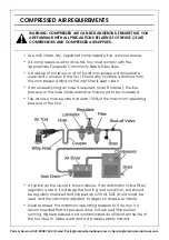
Page 7: ...ter may need to be increased The air hose must be rated at least 150 of the maximum operating pressure of the tool A typical air line layout is shown above If an automatic in line filter regulator is...

Page 8: ...4 Connect the other end of the hose to the compressor Your air tool is now ready for use You can fit a whip hose with a quick fit coupling if required available from your Clarke dealer INSTALLING THE...

Page 9: ...e tool and slip the spindle into the collet Secure in place by tightening the collar as above 2 Screw the sanding arbor onto the spindle and secure by tightening the nut against it using the larger wr...

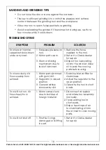
Page 10: ...bricant 1 Reduce the force applied to the tool 2 Return to Clarke dealer for repair 3 Drip air tool lubricating oil into the air inlet Allow oil to soak the moving parts before using Tool runs slowly...

Page 11: ...oil into the air inlet This should be carried out regardless of whether or not an in line mini oiler is used If an in line lubricator is not used this procedure should be repeated after every two to t...

Page 12: ...reduced compressor output excessive air demand from the airline moisture or restrictions in the air line or the use of connectors of improper size or poor condition which will reduce air supply Clarke...

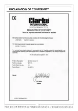
Page 13: ...13 Parts Service 020 8988 7400 E mail Parts clarkeinternational com or Service clarkeinternational com DECLARATION OF CONFORMITY...

Page 14: ...g 5 Roll Pin 25 Primary Gear 6 Roll Pin 26 Decorating Ring 7 O Ring 27 End Fixing Ring 8 O Ring 28 End Nut 9 Valve Stem 29 Gear Casing 10 Spring 30 Lubricating Nipple 11 O Ring 31 Bearing 12 Screw Cap...

Page 15: ...15 Parts Service 020 8988 7400 E mail Parts clarkeinternational com or Service clarkeinternational com PARTS DIAGRAM...

Page 16: ......

Reviews: