background image

4

ENGLISH

GENERAL FUNCTION EXPLANATION

Sensitivity Control

This adjustment is provided to adjust the ampli

fi

 er sensitivity so that it will produce 

maximum power given a variety of different input signal voltages. Setting this control 
correctly will ensure that you get maximum performance from your ampli

fi

 er and is critical 

to ensuring that minimal noise and distortion is produced.

Clarion recommends the use of an Oscilloscope or distortion detecting device such as the 
SMD DD-1 or DD-1+ Distortion Detector to properly set ampli

fi

 er sensitivity. A headroom 

setting of approximately 10dB will help to ensure that music that is recorded at low levels 
can still be reproduced at high volume levels. With this setting, it is the responsibility of the 
operator to use the ampli

fi

 er in a manner that will not produce audible distortion.

Procedure (Oscilloscope) Method:
1.  Obtain a test disc with a selection of Sine Waves recorded at -5dB and -10dB.
2.  Turn the gain all the way down on the ampli

fi

 er (to the left).

3.  Connect the ground terminal of the scope lead to the shield of the RCA cable 

coming from the source unit. 

Do no connect the scope lead to the speaker output 

terminals.

4.  Connect the scope probe to a speaker terminal on the channel you want to adjust.
5.  Select a Sine wave frequency that is well away from the chosen crossover frequency. 

For midrange speakers use 1kHz at -5dB, use 40Hz at -10dB for subwoofers.

6.  Turn the source unit up as high as possible without distortion.
7.  Monitor the output waveform of the amp on the scope.
8.  Increase the sensitivity of the ampli

fi

 er until the scope waveform shows a small 

fl

 at 

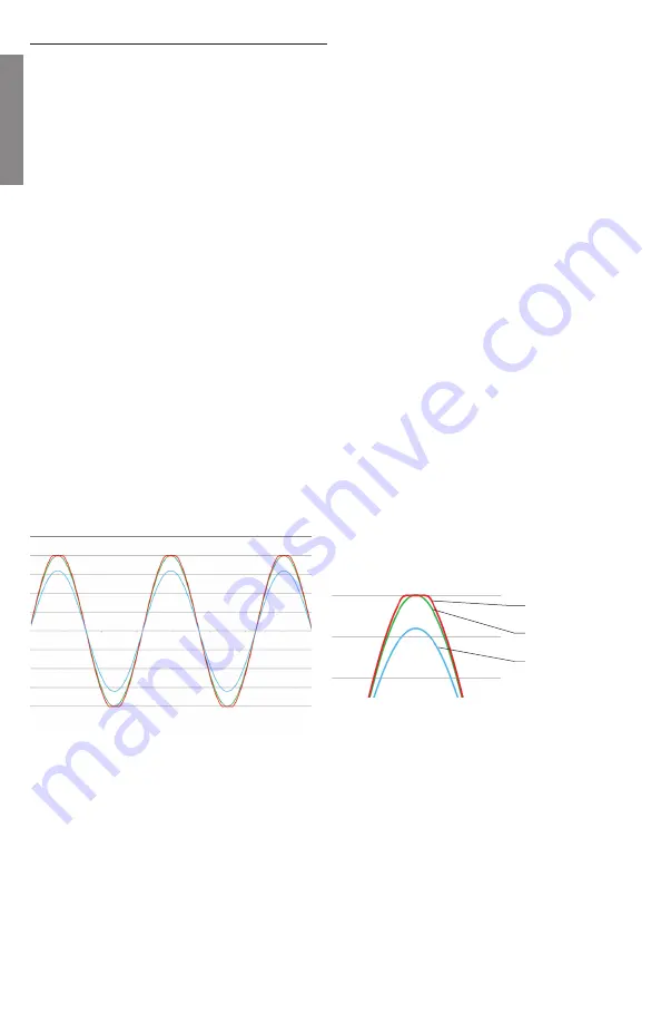
spot on the top or bottom of the waveform. See Figure 2 for an example of what to 
look for.

SMD DD-1 Method:
1.  Following the instructions provided with the DD-1, use the 0dB track to con

fi

 rm the 

output of the audio signal source is unclipped.

2.  Connect the DD-1 to the output of the ampli

fi

 er and use an appropriate -5dB or -10dB 

track. Increase the gain on the ampli

fi

 er until the Distortion LED illuminates

You should be able to turn the volume up to almost full (or wherever your source unit clips/
distorts) without hearing distortion. If you can’t turn the volume up most of the way without 
distortion, the sensitivity control is not adjusted properly.

Sine wave unclipped

Clipped Sine wave

Sine wave well bellow clipping

Fig 1 - Sine Wave at different Levels

Fig 2 - Close-Up of waveform

Summary of Contents for XC7120

Page 1: ...Owner s Installation Manual XC7120 Monoblock Class D Subwoofer Amplifier...

Page 2: ...cars or emergency vehicles Clarion wants you as a customer for life please be responsible at all times while enjoying your audio system Clarion takes no responsibility for any personal injury loss da...

Page 3: ...Output RCA Connection 17 Positive Speaker Output Terminals 18 Negative Speaker Output Terminals MARINE READY DESIGN All Clarion XC7 amplifiers are Marine Ready This means that the components used to c...

Page 4: ...source unit Do no connect the scope lead to the speaker output terminals 4 Connect the scope probe to a speaker terminal on the channel you want to adjust 5 Select a Sine wave frequency that is well a...

Page 5: ...en referenced to the chassis ground Remote Turn On Connection When 12V is applied to this terminal the amplifier will turn on When installing the amplifier with an after market source unit this wire i...

Page 6: ...o the XC7120 it gives you the ability to decrease the output level of the amplifier to fine tune the subwoofer level for the selection of music that is playing Always set the amplifier sensitivity gai...

Page 7: ...actory electrical connections under the hood of your vehicle be upgraded The industry refers to these upgrades as The Big 3 Performing these upgrades are optional but highly recommend Additional curre...

Page 8: ...um composites and high strength adhesives Clarion recommends running a ground wire of the same size as the power wire from the negative terminal of your battery to the ground location of your amplifie...

Page 9: ...o prevent a short circuit BC2 Remote Level Control Installation Clarion includes an remote subwoofer level control called the BC2 included in the box with all XC7 amplifiers When connected to the XC71...

Page 10: ...of the vehicle charging system Code 5 This error indicates that there is a DC voltage present on one of the speaker leads The amplifier will need to be serviced Code 6 There is an over current conditi...

Page 11: ...not drop below 10 6V Clarion recommends at least 4 AWG Pure Copper power wire for both 12V and GND connections Distorted Audio Input gain is not set properly Adjust as per instructions Source signal...

Page 12: ...12 ENGLISH SPEAKER WIRING DIAGRAMS XC7120 Single Dual 2 Ohm Subwoofer XC7120 Two Dual 4 Ohm Subwoofers Dual Voice Coil Subwoofer...

Page 13: ...CEA 2006A 700W x 1 1 0 THD 1 Ohm Power Output CEA 2006A 1100W x 1 1 0 THD Signal to Noise Ratio CEA 2006A 1W 4 Ohms 90 7 dBA Efficiency at Full Power 4 Ohms 87 10 Input Sensitivity 200mV to 4V Crosso...

Page 14: ...ons furnished by Clarion 4 This Limited Warranty does not cover static noise or other electrical interferences or labor costs for the removal or re installation of the unit for repair 5 The sole respo...

Page 15: ...RIGHTS WHICH VARY FROM STATE TO STATE 10 The laws of the State of California shall govern and control this limited warranty its interpretation and enforcement 11 Should you have any difficulties with...

Page 16: ...Clarion Canada Inc 3800A Laird Road Unit 6 Mississauga ON L5L 0B2 All Rights Reserved Copyright 2017 Clarion Canada Inc Printed in China...

Reviews: