background image

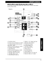
INPUT/OUTPUT CONNECTIONS AND AUDIO CONTROLS

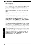
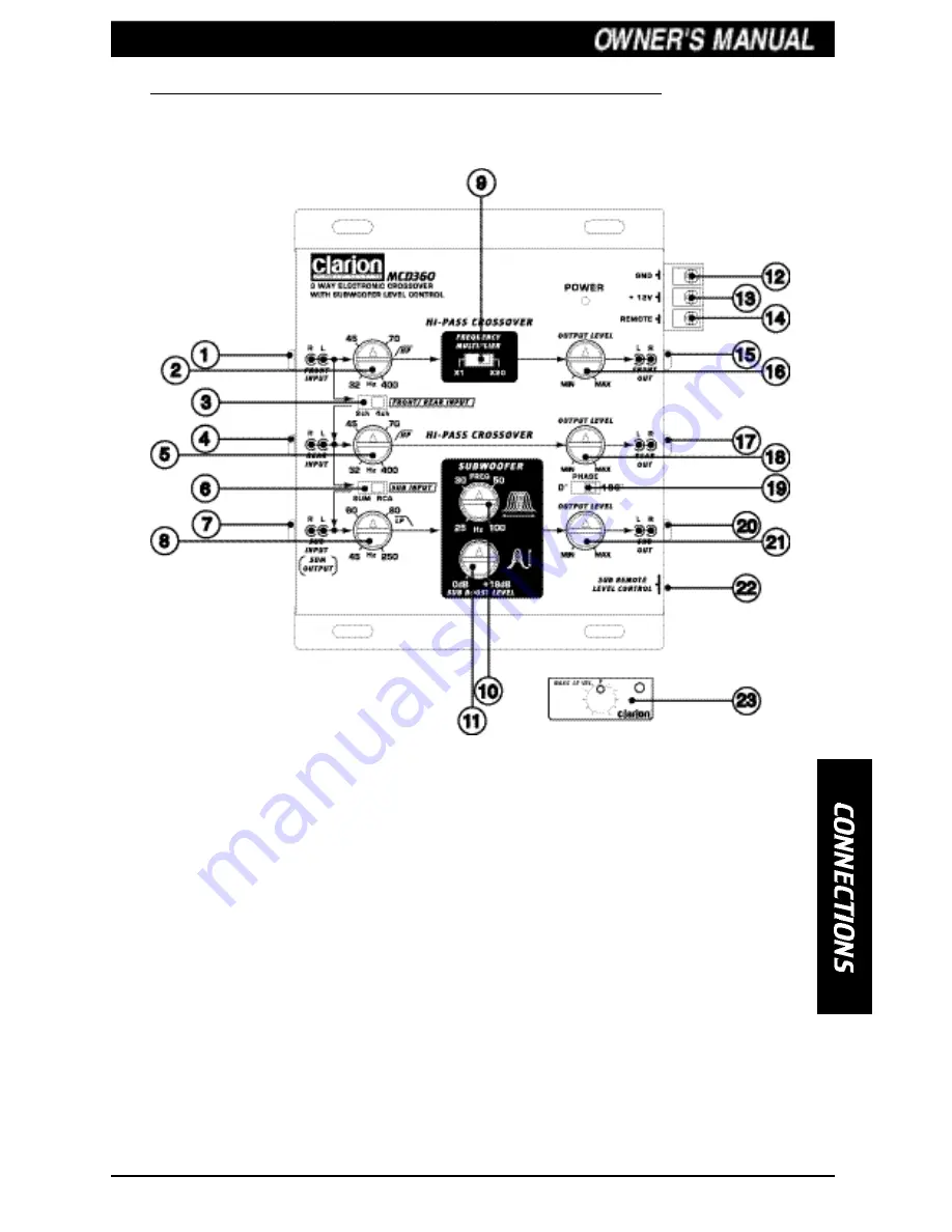
The top panel of MCD360 contains the controls for the crossover and output
levels as shown below.

3

1. Front RCA Input
2. Front Crossover Frequency Control
3. Front/Rear Input Selection Switch
4. Rear RCA Input
5. Rear Crossover Frequency Control
6. Sub Input Selection Switch
7. Sub RCAInput
8. Sub Crossover Frequency Control
9. Frequency Multiplier Switch
10. Sub Bass Boost Frequency
11. Sub Bass Boost Level
12. Ground Input Connector

13. B12V Input Connector
14. Remote Turn-On Input
15. Front RCA Output
16. Front Output Level
17. Rear RCA Output
18. Rear Output Level
19. Phase Switch
20. Sub RCAOutput
21. Sub Output Level
22. Remote Sub Level Connector
23. Remote Sub Level Control

Figure 1-

Summary of Contents for MCD360

Page 1: ......

Page 2: ...enjoying your new Clarion MCD360 Three Way Crossover please read the instructions listed in this manual Keep all instructions for future reference Please fill out and send in the enclosed warranty ca...

Page 3: ...er Frequency Control 6 Sub Input Selection Switch 7 Sub RCAInput 8 Sub Crossover Frequency Control 9 Frequency Multiplier Switch 10 Sub Bass Boost Frequency 11 Sub Bass Boost Level 12 Ground Input Con...

Page 4: ...Bass Boost circuit It acts much like an equalizer with adjustable gain from 0 18dB with a center frequency adjustable from 25Hz 100Hz Use this feature to tune low frequency audio response to compensa...

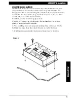
Page 5: ...et up mount the crossover so the front panel controls will be accessible after installation In addition observe the following precautions 1 Mount the crossover on a rigid surface Do not install the cr...

Page 6: ...e 3 when making electrical connections Connect the crossover s positive lead via a fuse directly to the positive terminal on the battery Use red insulated 18 gauge or larger wire for the crossover s p...

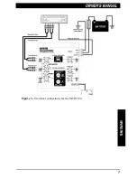
Page 7: ...7 Figure 3 Electrical connections for the MCD 360...

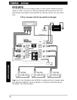
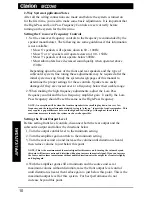
Page 8: ...hich system best fits your requirements thoroughly read and follow the directions below for your system type 2 Way System with Front and Rear Output 8 Figure 4 In this illustration the MCD360 is confi...

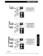
Page 9: ...channel input configure switches as shown For 4 channel input with front and rear fade configure switches as shown For front and rear fade with dedicated subwoofer input configure switches as shown F...

Page 10: ...quency should be set the same as the High Pass frequency NOTE An exception will be when the front rearspeakeris too small to play down to a very low frequency and the subwoofersounds distorted trying...

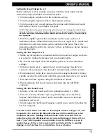
Page 11: ...cable 2 Be sure the sub output level and amplifier gains are at their minimum settings 3 With the volume set at a medium level slowly increase the sub level control to the point where the subwoofer v...

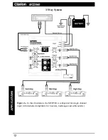
Page 12: ...3 Way System 12 Figure 6 In this illustration the MCD360 is configured for single channel input with dedicated amplifiers for tweeters midranges and subwoofer s...

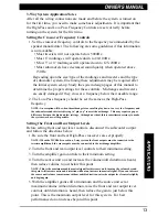
Page 13: ...d trying to play up to meet the midrange This may require a gap or difference between the high and low settings Although not ideal this is sometimes necessary to make the system work as well as possib...

Page 14: ...c and slowly increase the Sub Boost control until a noticeable increase in low bass response is perceived 3 Slowly adjust the Sub Boost Frequency control up or down to realize the best bass response C...

Page 15: ...s on the same side proceed on Swap the left and right High Pass RCAs at the amplifier input If the problem trades sides in the vehicle then the RCA cable is defective If the problem stays on the same...

Page 16: ...661 W Redondo Beach Blvd Gardena CA 90247 1 800 GO CLARION www clarion usa com MCD360 10 Rev 1 02 00...

Reviews: