background image


20 

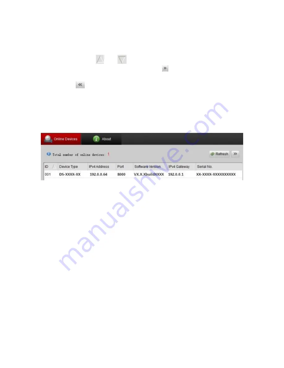
  You can also click 

Refresh Every 15s

 to refresh the online 

device list manually. The newly searched devices are added 

to the list. 

  You can click 

  or 

  on each column heading to order 

the information. You can also click    to show the device 

table and hide the network parameter panel on the right side, 

or click 

  to show the network parameter panel. 

To modify device information: 

1. 

Select the device to be modified from the device list, as 

shown below.   


2. 

The network parameters of the device will be displayed in 

the Modify Network Parameters panel on the right side, as 

shown below. 

Summary of Contents for Mainline CV-M13B10-ODI

Page 1: ...Doc ID 2014 08 338 REV 02 Network Camera Installation Guide 1 3 MP Mainline Bullet Camera...

Page 2: ...and international copyright law Trademarks and patents The 1 3 MP Mainline Bullet Camera name is a trademark of Clare Controls Inc Other trade names used in this document may be trademarks or register...

Page 3: ...4 Wiring 6 Installation 6 Before you start 7 Mounting 11 View angle adjusting 15 Zoom and focus adjusting 17 Setting the network camera over the LAN 18 Accessing via a web browser 22 System requireme...

Page 4: ...arm I O and a micro SD slot for up to 32 GB local memory are also included Package contents 1X 12 V power supply 4X anchor screws 4X plastic anchors 1X drill template 1X composite video output pigtail...

Page 5: ...not connect several devices to one power adapter as adapter overload may cause over heating or a fire hazard Make sure that the plug is firmly connected to the power socket When the product is mounted...

Page 6: ...S may be burned out by a laser beam so when laser equipment is in use make sure that the surface of CMOS will not be exposed to the laser beam Do not expose the camera to high electromagnetic radiatio...

Page 7: ...utput interface 8 Integrated bracket 9 Reset button 10 SD card slot 11 Power interface 12 Network interface Note To reset the default parameters to the camera press and hold the reset button and power...

Page 8: ...5 The bullet camera supports audio and alarm functions The interfaces are shown in Figure 2 Figure 2 Audio and alarm interfaces 1 Audio 2 Alarm 1 2...

Page 9: ...6 Wiring Wire your bullet camera as shown in Figure 3 Figure 3 Wiring Installation To ensure the camera operates properly install the camera according to the instructions below...

Page 10: ...mine the proper environmental operating conditions refer to Specifications on page 27 Make sure the power supply matches the required voltage to avoid damage If the product does not function properly...

Page 11: ...8 To mount the SD card 1 Rotate the TW M3 5 screw counterclockwise about 3 to 4 rounds to loosen it Slide the sun shield according to the arrow direction as shown in the figure below left Turn screw...

Page 12: ...counterclockwise as shown in the figure above right 4 Insert the SD card to the SD card slot 5 Place the cover back on the front of the camera and rotate it clockwise as shown Reinstall the sun shiel...

Page 13: ...tate the TW M3 5 screw clockwise to tighten the sun shield Note For waterproofing align the rotating label on the front cover with that on the camera when you rotate the front cover clockwise Rotating...

Page 14: ...directly or it can be mounted to a wall with a junction box not included or a gang box not included To mount directly to the wall 1 Attach the drill template to the wall where the camera is to be moun...

Page 15: ...ing cut a cable hole according to the drill template Skip this step if you want to route the cables on the surface of the ceiling 4 Route the cables of the camera 1 1 1 1 2 2 2 2 1 Screw Hole for Brac...

Page 16: ...or ceiling with expansion screws as shown below To mount with a junction box 1 Attach the drill template to the wall where the camera is to be mounted 2 Drill holes in the wall according to the numbe...

Page 17: ...e junction box to the wall with expansion screws 5 Route the cables of the camera 6 Connect the video output connector to the monitor and the power connector to the power supply Adjust the image and f...

Page 18: ...is pan tilt rotation adjusting allows adjustment for optimum camera rotation and placement You can use this function to get the angle of view that you want To adjust pan 1 Loosen the lock screw 1 2 Ad...

Page 19: ...from 0 degrees to 90 degrees 3 Tighten the lock screw 2 To adjust rotation 1 Loosen the lock screw 3 2 Rotate the rotation position to adjust the azimuth angle of the image The adjusting range is fro...

Page 20: ...emble the camera 2 View the camera image using the monitor 3 Loosen the zoom lever and move the lever between T Tele and W Wide to obtain the appropriate angle of view 4 Tighten the zoom lever 5 Loose...

Page 21: ...the IP of network camera The following figure shows the cable connection of network camera and PC Figure 4 Wiring over LAN To set the IP address of the camera for accessing via LAN 1 To get the IP add...

Page 22: ...rom the subnet where your computer is located It displays the total number and information of the searched devices in the Online Devices interface The interface displays the device type IP address por...

Page 23: ...information You can also click to show the device table and hide the network parameter panel on the right side or click to show the network parameter panel To modify device information 1 Select the de...

Page 24: ...ple IP address and port number 4 Enter the password of the admin account of the device in the Password field and click Save to save the changes 5 Enter the IP address of the network camera in the addr...

Page 25: ...ve version Vista Win7 Server 2003 Server 2008 32 bits CPU Intel Pentium IV 3 0 GHz or higher RAM 1 G or higher Display 1024 768 resolution or higher Web browser Internet Explorer 7 0 and above Apple S...

Page 26: ...all the plug in before viewing the live video and managing the camera Follow the installation prompts to install the plug in Note You may need to close the web browser to finish the installation of th...

Page 27: ...24 5 Click OK...

Page 28: ...25 6 Click Next 7 Click Finish...

Page 29: ...8 Reopen the web browser after the installation of the plug in and repeat steps 2 and 3 to login Note For detailed instructions of further configuration refer to the Network Camera User Guide Doc ID 3...

Page 30: ...mat H 264 MJPEG Frame rate 50 Hz 25 fps 1280 960 25 fps 1280 720 60 Hz 30 fps 1280 960 30 fps 1280 720 it rate 32 Kbps 16 Mbps On board storage Built in Micro SD card slot up to 32 GB Digital noise re...

Page 31: ...02 3 af Power consumption Max 5 5 W 7 5 W with ICR on Environmental Temperature 22 to 140 F 30 to 60 C Relative humidity 0 to 95 noncondensing Mechanical Housing IP66 Dimension 3 74 4 13 10 18 in 9 5...

Page 32: ...WHATSOEVER REGARDING THE PERFORMANCE OR RELIABILITY OF ANY SECURITY OR SIGNALING RELATED FUNCTIONS OF THIS PRODUCT FCC This device complies with part 15 of the FCC Rules Operation is subject to the f...

Page 33: ...r more information see www recyclethis info 2006 66 EC battery directive This product contains a battery that cannot be disposed of as unsorted municipal waste in the European Union See the product do...

Page 34: ...31 Contact information Clare Controls Inc 7519 Pennsylvania Ave Suite 104 Sarasota FL 34243 Support 941 404 1072 Fax 941 870 9646 http support clarecontrols com www clarecontrols com...

Page 35: ......

Page 36: ......

Reviews: