


2 / 4
Doc ID - 724 • REV 07
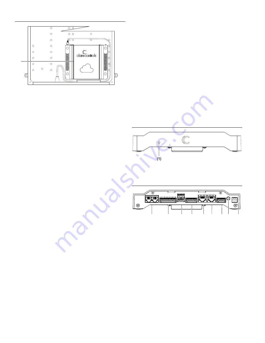
Figure 1: CLIQ.lite mounted in a structured enclosure
(1) Mount CLIQ.lite with cable ties
Connecting devices to the CLIQ.lite
After placing your CLIQ.lite, make the connections to your
other devices. Figures 2 and 3 identify the LEDs and ports on
the front and rear of the CLIQ.lite. Refer to the documentation
that came with each of your other devices for detailed
information about connecting those devices to the CLIQ.lite.
To connect the CLIQ.lite:
1. Connect your serial devices (optional) to either of the two
RS-232 ports using an RJ12 to RS-232 cable, or an RJ12
to DB9 null modem cable (included). See Figure 3, item 1.
For RJ12 pinouts, see Figure 6.
2. Connect your IR devices (optional) to the 12-pin terminal
connector (included), and then insert the connector into
the port labeled “IR Outputs.” See Figure 3, item 2.
If your IR device comes with a 3.5 mm connector, you will
need to cut and strip the wires before connecting it to the
terminal connector.
Note:
When connecting an IR emitter (included), attach
the striped wire to positive (+) and the black wire to
negative (-).
3. Connect a CS-BR-1 Streams Audio Bridge (optional) to a
USB port on the CLIQ.lite. See Figure 3, item 3.
Note:
The USB connection allows the CS-BR-1 to encode
up to three simultaneous audio streams onto the CobraNet
network.
4. Connect your digital I/O devices (optional) to the 8-pin
terminal connector, and then insert the terminal connector
into the port labeled “I/O.” See Figure 3, item 4.
When connecting devices, wire it such that ports 1 and 2
share the same 12 VDC power and ground and ports 3
and 4 share the same power and ground.
5. Use and Ethernet cable (not included) to connect your
CobraNet switch to the port labeled “CobraNet.” See
Figure 3, item 5.
Note:
The CobraNet port is preset with the static IP
address 172.30.100.1. All CobraNet devices used on the
same subnet must use an address from 172.30.100.2 to
172.30.100.254.
6. Use an Ethernet cable (not included) to connect to your
data network switch to the port labeled “Ethernet.” See
Figure 3, item 6.
Notes
The Network port is preset to DHCP. If you are using
the Streaming Media server in your project, a fixed IP
address is not required and should be configured as
“localhost.”
If you are using a device, such as an RTI remote that
requires the controller to have a fixed IP, you must set
the fixed IP using a MAC/DHCP reservation on the local
router.
7. Connect relay contacts (e.g., garage door contacts) to the
6-pin terminal connector, and then insert the terminal
connector into the port labeled “Relay.” See Figure 3,
item 7.
8. Attach the Z-Wave antenna or optional Z-Wave antenna
extender to the Z-Wave port. See “Attaching the Z-Wave
antenna” below.
Figure 2: CLIQ.lite front
(1) LED – It illuminates purple when booting and blue when running
normally
Figure 3: CLIQ.lite rear connections
(1) RS-232 (2 ports)
(2) IR Outputs
(3) USB port
(4) I/O
(5) CobraNet
(6) Ethernet
(7) Relay
(8) Z-Wave antenna
(9) Power – 12 VDC
Attaching the Z-Wave antenna
The Z-Wave antenna can be mounted to the CLIQ.lite
controller, or further away using an extender cable (included)
to enhance radio performance. When mounting the CLIQ.lite
inside a structured enclosure, always mount the antenna
outside the enclosure using the extender cable.
To attach the antenna directly to the CLIQ.lite:
1. Remove the Z-Wave antenna from its packaging.
2. Screw antenna to the antenna port on the rear of the
CLIQ.lite until the antenna is snug. Do not over-tighten the
antenna. See Figure 4.
(1)
RS232
IR Outputs
USB
I/O
CobraNet Ethernet
Relay
#1
#2
12vdc
Networks
#1
#2
1 2 3 4 5 6
12
vd
c
G
nd
#3
#1
#2
12
vd
c
G
nd
#4
N
C
N
O C NC NO C
(1)
(2)
(3)
(4)
(5) (6)
(7) (8)
(9)


