The settings described below are for optimal operation of the tying system.
Failure to follow them may cause tying errors.
A. Main settings:
QUADRANT 5300
The 10 steps for tying adjustment
This simplified operating manual does not replace the manual supplied with the machine.
All the safety guidelines given in this manual must be observed when working with the baler.
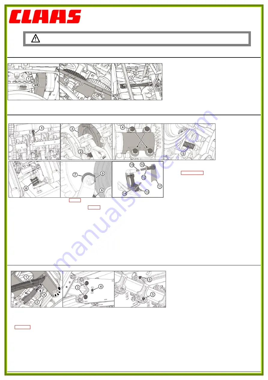
Step 1: 1-1
Turn the flywheel in the direction of the arrow to position
the piston at front dead center.
In this position, the identification mark (1) must be centered on the
crank hole.
The identification mark (2) on the crank wheel must be across from
the hole in the left side plate.
1-2
If necessary, change the position of the driveshaft (3):
-
Position the crank wheel and lock it.
-
Remove the 2 sides of the driveshaft.
-
Put the piston at top dead center and tighten the flywheel brake.
-
Look for the best position by turning and repositioning the
driveshaft.
B. Knotter settings:
Step 2: 2-1
Disconnect the tie rod (1) and
pivot the knotter to
maintenance position.
The clearance between the pinion (2) and the disk (3) must be
between 0.05 and 0.2 mm.
2-2
If necessary, adjust the clearance between the pinion and the
disk:
-
Loosen the 4 bolts (4).
-
Place a chock between the pinion and the disk,
-
Press the knotter to bring the pinion into contact with the chock.
Press the knotter cap to in the opposite direction.
-
Tighten the 4 bolts (4) to torque of: 63 Nm,
-
Remove the chock,
-
Pivot the knotter on the shaft; it must turn freely with no sticking
points.
Step 3: 3-1
Adjust the knotter nose spring (5): 33
+1
mm.
3-2
Check that the roller (7) is not in contact with the disk.
Adjust the length of the spring (6) for the twine pincer flange: 28
+1
mm.
Step 4: 4-1
Put the roller into contact with the excrescent part (8).
4-2
Adjust the roller (7) using its eccentric shaft: The clearance between the roller and the part (8) must be zero. The roller (7) must be difficult to turn by hand. The lever must always be in
contact with the pin (9).
4-3
Pivot the knotter into position.
Step 5: -
Unclip the ball joints (10) from each knotter.
- Pull the drive shaft (11) backward to capture the clearance.
- Loosen the nut (12) and press the twine guide finger (13) to the stop on the cornet (14).
- Screw or unscrew the ball joint (10) until it is across from the ball on the drive shaft (11). (The ball joint must be able to fit onto the ball without displacing either the twine guide finger (13) or
the drive shaft (11).)
- Screw the ball joint (10) 1 turn on the connecting rod (15) and lock the ball joint (10) into position with the nut (12).
- Clip the ball joint (10) to the ball of the drive shaft (11).
Note: When using very thick twine, it may be useful to screw the ball joint (10) one extra turn.
C. Needle settings:
Step 6: 6-1
Launch tying manually.
Turn the flywheel in the direction of the arrow to align the wheel axis (1) with the twine pincer flange (2).
Pull the knotter backward to capture the clearance.
6-2
Measure the distance (X) between the lower edge of the needle and the upper edge of the twine pincer flange:
X = 8
± 1
mm
6-3
If necessary, change the height of the needle:
-
Release bolts (3) and (4).
-
Change the needle’s position using the bolts (5).
-
Tighten the bolts (3) to 150 Nm.
-
Tighten the bolt (4) to 24.5 Nm.
00 0288 280 0
– EN-US – 09.2016


