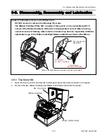


3-5. Disassembly, Reassembly and Lubrication
3-21
CLP-621 & CLP-631
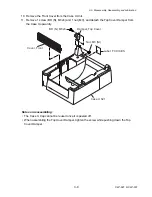
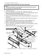
3-5-11. Main PCB Unit and Centro PCB Unit
1. Remove the Case U Unit. Refer to 3-5-2 “Case U”.
2. Remove the Main PCB Block. Refer to 3-5-10 “Main PCB Block, Power Supply Unit and
Control Panel Unit”.
3. Remove 2 screws (BHT (ST), M3x5) and 2 washers (EXT. T, 3 (N
I
)), and then detach the
Centro PCB Unit.
4. Disconnect the Centro Cable SA from the Centro PCB Unit and the Main PCB Unit.
5. Remove the Main PCB Sheet 2 from the Main PCB Unit.
6. Remove 2 lock screws and 4 screws (PHT (ST#3), M3x5), and detach the Main PCB Unit and
the Main PCB Sheet from the Main PCB Plate.
Plate, Main PCB
PHT (ST#3), M3x5
BHT (ST), M3x5
Lock Screw
SA, Centro Cable
Unit, Main PCB
Unit, Centro PCB
EXT. T, 3 (NI)
Sheet, Main PCB
Sheet 2, Main PCB
Note on reassembling:
• When the Main PCB Unit is replaced with new one, perform the sensor adjustment. Refer to
3-6-1 “Transparent/Reflective Sensor Position Adjustment” on page
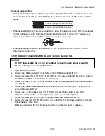
PHT (PT2T), M3x6
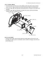
3-5-12. Ope-Pane PCB SA
LED, Window
1. Remove the Case U Unit. Refer to 3-5-2
“Case U”.
Cover, Ope-Pane
2. Remove the Control Panel Unit. Refer to
3-5-10 “Main PCB Block, Power Supply Unit
and Control Panel Unit”.
SA, Ope-Pane PCB
3. Remove 3 screws (PHT (PH2T), M3x6) and
detach the Ope-pane Cover.
4. Remove the Key Switch and the Window LED
from the Ope-pane PCB SA.
Switch, Key
Summary of Contents for CLP-621
Page 1: ...Technical Manual CLP 621 CLP 631 Thermal Transfer Barcode Label Printer JM74961 00F 1 00E 0701...
Page 2: ...CLP 621 CLP 631 ii Copyright 2007 by CITIZEN SYSTEMS JAPAN CO LTD...
Page 4: ...CHAPTER 1 SPECIFICATIONS CLP 621 CLP 631...
Page 13: ...CHAPTER 2 OPERATING PRINCIPLES CLP 621 CLP 631...
Page 73: ...CHAPTER 3 DISASSEMBLY AND MAINTENANCE CLP 621 CLP 631...
Page 126: ...CLP 621 CLP 631 CHAPTER 4 TROUBLESHOOTING...
Page 138: ...CLP 621 CLP 631 CHAPTER 5 PARTS LISTS...
Page 166: ...Chapter 5 Parts Lists CLP 621 CLP 631 5 29 DRAWING NO 7 Control Panel Unit Rev 0 4 3 2 1 5...
Page 177: ...Chapter 5 Parts Lists CLP 621 CLP 631 5 40 DRAWING NO 10 Accessories Rev 0 3 2 4 1...
Page 179: ...CHAPTER 6 CIRCUIT DIAGRAMS CLP 621 CLP 631...
Page 208: ...APPENDICES CLP 621 CLP 631...
Page 212: ...B Mounting Diagrams AP 5 CLP 621 CLP 631 Main PCB Solder side...
Page 214: ...B Mounting Diagrams AP 7 CLP 621 CLP 631 B 3 Ribbon Main PCB Parts side Solder side...
Page 217: ......


