


3-6. Adjustments
3-6. Adjustments
CLP-621 & CLP-631
3-40
3-6-1. Transparent/Reflective Sensor Position Adjustment
When you replace one of the following parts, perform both sensor position adjustment and sensor
sensitivity adjustment.
• Main PCB Unit
• Transparent Sensor PCB SA
• Reflective Sensor PCB SA
(1) Sensor position adjustment (factory mode)
After entering Factory mode, adjust the following submenu items:
• Through Sensor Position
• Reflect Sensor Position
For details, refer to
2-3-2-(3-3)-(a) “Factory mode menu table”
.
(2) Sensor sensitivity adjustment (maintenance mode)
In this adjustment, since the printer has not a display, PC is used instead.
All operations will be done with the keys on the printer’s control panel.
Communication between the printer and a PC is made through the serial port.
(2-1) Preparation
Before starting adjustment, prepare the following items:
• Media (both label paper and tag) (recommended media or media you use)
• RS-232C serial cable
• PC which is installed Terminal software such as HyperTerminal and TeraTerm.
Windows normally comes with the HyperTerminal. If the software is not installed, you
need to install it.
* Windows® is a registered trademark of Microsoft Corporation in the United States
and/or other countries.
Setting on the PC side:
Make the following settings on the PC beforehand:
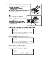
1. Connect the RS-232C serial cable between the printer and the PC.
2. On the PC, start the Terminal software.
3 Set the transmission conditions on the Terminal software so that they are identical to
those on the printer side.
Default values of the printer:
• Transmission speed (baud rate): 9,600 bps
• Data length:
8 bits
• Stop bit:
1 bit
• Protocol:
XON/XOFF
Summary of Contents for CLP-621
Page 1: ...Technical Manual CLP 621 CLP 631 Thermal Transfer Barcode Label Printer JM74961 00F 1 00E 0701...
Page 2: ...CLP 621 CLP 631 ii Copyright 2007 by CITIZEN SYSTEMS JAPAN CO LTD...
Page 4: ...CHAPTER 1 SPECIFICATIONS CLP 621 CLP 631...
Page 13: ...CHAPTER 2 OPERATING PRINCIPLES CLP 621 CLP 631...
Page 73: ...CHAPTER 3 DISASSEMBLY AND MAINTENANCE CLP 621 CLP 631...
Page 126: ...CLP 621 CLP 631 CHAPTER 4 TROUBLESHOOTING...
Page 138: ...CLP 621 CLP 631 CHAPTER 5 PARTS LISTS...
Page 166: ...Chapter 5 Parts Lists CLP 621 CLP 631 5 29 DRAWING NO 7 Control Panel Unit Rev 0 4 3 2 1 5...
Page 177: ...Chapter 5 Parts Lists CLP 621 CLP 631 5 40 DRAWING NO 10 Accessories Rev 0 3 2 4 1...
Page 179: ...CHAPTER 6 CIRCUIT DIAGRAMS CLP 621 CLP 631...
Page 208: ...APPENDICES CLP 621 CLP 631...
Page 212: ...B Mounting Diagrams AP 5 CLP 621 CLP 631 Main PCB Solder side...
Page 214: ...B Mounting Diagrams AP 7 CLP 621 CLP 631 B 3 Ribbon Main PCB Parts side Solder side...
Page 217: ......


