


2-2 Interface introduction
2-2-1
Power supply
The applicable voltage for power supply is 12-24
Vdc/ac or 120-230Vac (two different versions)
(please refer to 1-3-2).
2-2-2 RS485
ports
RS485 ports is designed for communicating with
remote computer to transmit the detecting data
and monitoring instructions : this system uses
half-duplex communication by the way of Modbus
transmission protocol. RS485 communication
cable in general is using twisted pair, but under the
high requirement of environment suggest to use
shielded twisted pair cables, to achieve perfect
performance of anti-interference.
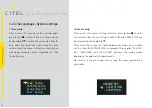
2-2-3 Sensor
LSCM-D equipped with dedicated coil sensor for surge measuring : two
versions ar available for different detection range. The sensor should be
mounted around the discharge conductors as fig4 shows. The connection
wire (default configuration) should connect to monitoring unit.
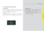
2-2-4 Switching signal-Alarm inputs
The device is equipped with two alarm input ports for monitoring the
switching state from SPD and/or disconnectors. The received switching
state information will transfer to the alarm output port and remote
computer through RS485 in real time. Tthe “alarm” process can be
triggered by setting the fault state for each input ports.
2-2-5 Alarm output
Output port is designed for trigger the "alarm" process like LED/buzzer/-
contactor. The output signal status totally depends on the input signal
status. The maximum operating voltage and current for output ports is
350Vdc & 120mA.
08
LSCM-D User Manual
2-Installation