© 2008 Cisco Systems, Inc. All rights reserved.
4
Configuration
The UC500 may be configured with either the Cisco Configuration Assistant
(CCA) or command line interface (CLI). This guide documents the CCA
configurations tasks as far as possible with CLI used only to customize the
template further to work with the provider.
4.1
Installation
Please refer to the “Getting Started Guide” located at
http://www.cisco.com/en/US/products/ps7293/products_getting_started_guide091
86a0080824095.html
for instructions about physically connecting the UC500’s
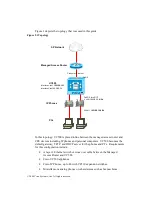
ports. To summarize:
•
Connect the “WAN” port to the same Ethernet segment as the inside
interface of the Managed Access Router. This may be accomplished
either with a crossover cable or with a LAN switch.
•
Connect IP phones to the FastEthernet ports on the front of the UC500.
•
PCs should generally be connected to the switch port on the phones.
•
Any analog devices (such as faxes) may be connected to the FXS ports on
the UC500.
Install CCA on a PC connected to one of the FastEthernet ports on the front of the
UC500. Make sure this PC is configured for DHCP to receive an IP address from
UC500.
4.2
Initial Configuration
If the UC500 platform has been configured for testing or other purposes prior to
the customer installation, be sure to reset it to the factory default configuration.
UC500 ships with the factory default configuration files on its compact flash, for
example “UC500-16U-4FXO-K9-factory-4.2.5.cfg”. The exact name of this file
depends on the UC500 model but the procedure to restore the configuration to the
factory default is the same: Using a console connection, copy this file to the
startup-config in NVRAM. For example:
UC500#copy flash:UC500-16U-4FXO-K9-factory-4.2.5.cfg startup-config
Destination filename [startup-config]?
[OK]
11553 bytes copied in 2.340 secs (4937 bytes/sec)
UC500#
Then reload the UC500.

