5
2
Installing the Cisco uBR925 Cable Access Router
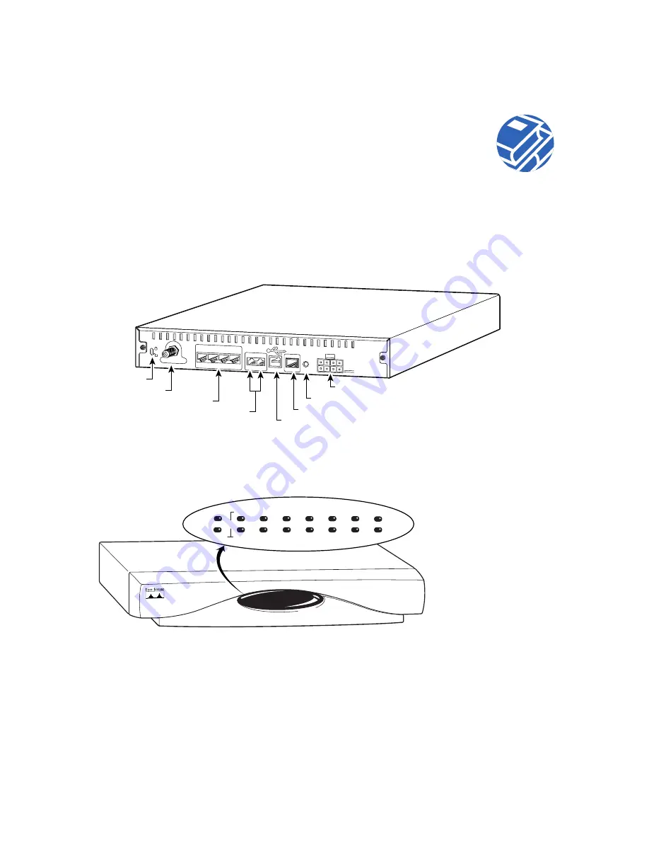
This section provides the basic information necessary to install the Cisco uBR925 Cable Access
Router. Figure 1 shows the locations for connecting all cables to the connectors on the rear panel of
the Cisco uBR925 Cable Access Router. Use this diagram as a guide to connecting the required cables.
Figure 1
Cisco uBR925 Cable Access Router Rear Panel
Figure 2 identifies the LEDs on the front panel of the Cisco uBR925 Cable Access Router.
Figure 2
Cisco uBR925 Cable Access Router LEDs
36035
Cable TV In
Reset
Power
5V
X
Ethernet 0
X
X
X
1
2
3
4
Cisco uBR925
Console
Phone
v1+v2 v2
USB
Cable F-connector
Lock
Reset switch
Power receptacle
Ethernet 10BaseT (RJ-45)
Console (RJ-45)
USB port
Phone (RJ-11)
36036
Cisco uBR900
SERIES
OK
ACT
LINK
UPS
1
2
3
4
USB
DS
V OK
V1
V2
US
DSNR
MSG
CATV


