


Product Overview 1-25
Physical Description
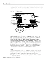
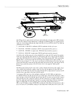
Ethernet Interface Processor (EIP)
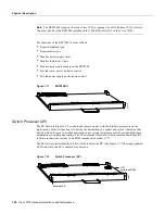
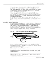
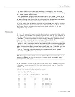
The EIP, shown in Figure 1-15, provides two, four, or six Ethernet ports that operate at up to
10 Mbps. Each port supports both Ethernet Version 1 and IEEE 802.3/Ethernet Version 2 interfaces.
A bit-slice processor provides a high-speed data path between the EIP and other interface processors.
The default EIP microcode resides on a ROM in socket U101.
Figure 1-15
Ethernet Interface Processor (EIP)
As with the other interface processors, the enabled LED is on when the EIP is enabled for operation.
The three LEDs for each port indicate the following:
•
Receive—Frames are being received.
•
Transmit—Frames are being transmitted.
•
Collision—A frame collision has been detected.
For complete descriptions of the LED states, refer to the appendix “Reading LED Indicators.”
The EIP is available with two, four, or six ports. The Cisco 7010 supports up to three EIPs for a
maximum of 18 Ethernet ports. Each port requires an Ethernet transceiver or a media attachment unit
(MAU) and attachment unit interface (AUI) cable to connect to the external network. For
descriptions of Ethernet transceivers and AUIs, refer to the section “Ethernet Connection
Equipment” in the chapter “Preparing for Installation.” For descriptions of Ethernet network
connections, refer to the section “Ethernet Connections” in the chapter “Installing the Router.”
Each port on the EIP automatically supports both Ethernet Version 1 and Version 2/IEEE 802.3
connections. When an interface is connected to an EIP port, the port automatically adjusts to the
interface type. The ports are independent, so you can mix both versions on one EIP.
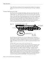
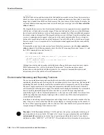
Fast Ethernet Interface Processor
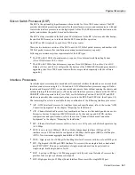
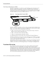
The FEIP provides up to two 100-Mbps, IEEE 802.3u 100BaseT ports. (Figure 1-16 shows a
two-port FEIP.) IEEE 802.3u specifies several different physical layers for 100BaseT:
100BaseTX—100BaseT half duplex, over Category 5, unshielded twisted-pair (UTP),
EIA/TIA-568-compliant cable; 100BaseFX—100BaseT full duplex, over twisted pair or optical
fiber); and 100BaseT4—100BaseT full duplex, using Category 3 and 4 cabling with four pairs (also
called 4T+).
H2005
U101,
microcode ROM
Enabled
0
1
2
3
4
5
Collision
Transmit
Receive
Summary of Contents for TelePresence Server 7010
Page 10: ...x Cisco 7010 Hardware Installation and Maintenence ...
Page 14: ...iv Cisco 7010 Hardware Installation and Maintenance Document Conventions ...
Page 148: ...3 36 Cisco 7010 Hardware Installation and Maintenance Using the Flash Memory Card ...
Page 158: ...4 10 Cisco 7010 Hardware Installation and Maintenance Troubleshooting the Processor Subsystem ...
Page 242: ...5 84 Cisco 7010 Hardware Installation and Maintenance Replacing Internal Components ...
Page 258: ...A 16 Cisco 7010 Hardware Installation and Maintenance MIP Interface Cable Pinouts ...
Page 270: ...B 12 Cisco 7010 Hardware Installation and Maintenance Interface Processor LEDs ...
Page 274: ...C 4 Cisco 7000 Hardware Installation and Maintenance ...
Page 287: ...Index 13 ...


