


Product Overview 1-11
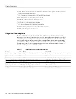
Physical Description
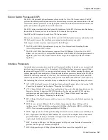
Route Processor (RP)
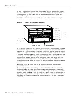
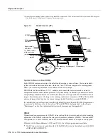
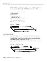
The RP, shown in Figure 1-9, is the main system processor in the router. The RP contains the system
central processing unit (CPU), the system software, and most of the system memory components,
and it maintains and executes the management functions that control the system. The RP contains
the following components:
•
25-MHz Motorola MC68040 CPU for processing key functions that are not time-critical.
•
System hardware configuration register for setting default boot instructions.
•
Bank of hardware (MAC-layer) addresses for the interface ports.
•
Most of the memory components used by the system, including the eight erasable programmable
read-only memory (EPROM) components that contain the default system software (Although
these components actually are EPROMs, they are commonly referred to as the software or boot
ROMs.).
•
Air-temperature sensors for environmental monitoring.
In addition to the preceding system components, the RP contains and executes the following
management functions that control the system:
•
Sending and receiving routing protocol updates
•
Managing tables and caches
•
Monitoring interface and environmental status
•
Providing SNMP management and the console/Telnet interface
The RP must be installed in the top processor slot, which is labeled RP.
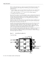
Memory Components
Table 1-3 lists the functions of the various types of memory on the RP, and Figure 1-9 shows the
locations of each.
Table 1-3
RP Memory Components
Memory
Type
Size Quantity
Description
Location
EPROM
1
1. Although these components actually are EPROMs, they are commonly known as the software or boot ROMs.
4 Mb
2
2. The size (capacity) of the software EPROMs changes as needed to accommodate the size of the system software image. Software
Releases 9.17(6) and earlier reside on 2-Mb EPROMs, Software Release 9.17(7) resides on 4-Mb EPROMs, and the size of future
software releases is likely to increase.
8
4-Mb EPROMs
ROM1–ROM8 (see the chapter
“
”)
DRAM 16 MB
or
64 MB
4
4
4-MB SIMMs
16-MB SIMMs
SIMMS sockets U35, U36, U58, U59
NVRAM 128
KB
1
128
KB
U120
Flash memory
4 MB
16
256-KB Flash memory
components
U14–U17, U27–U30, U45–U48, U60–63
Flash memory
card
3
8 or
16 MB
1
PCMCIA Flash memory
card
Flash memory card slot on faceplate
EEPROM
–
1
Board-specific information,
address allocator
U108
Summary of Contents for TelePresence Server 7010
Page 10: ...x Cisco 7010 Hardware Installation and Maintenence ...
Page 14: ...iv Cisco 7010 Hardware Installation and Maintenance Document Conventions ...
Page 148: ...3 36 Cisco 7010 Hardware Installation and Maintenance Using the Flash Memory Card ...
Page 158: ...4 10 Cisco 7010 Hardware Installation and Maintenance Troubleshooting the Processor Subsystem ...
Page 242: ...5 84 Cisco 7010 Hardware Installation and Maintenance Replacing Internal Components ...
Page 258: ...A 16 Cisco 7010 Hardware Installation and Maintenance MIP Interface Cable Pinouts ...
Page 270: ...B 12 Cisco 7010 Hardware Installation and Maintenance Interface Processor LEDs ...
Page 274: ...C 4 Cisco 7000 Hardware Installation and Maintenance ...
Page 287: ...Index 13 ...


