


A-4 Cisco 7010 Hardware Installation and Maintenance
Fast Ethernet Connector Signals
Fast Ethernet Connector Signals
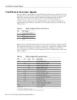
The two connectors on the FEIP are a single MII, 40-pin, D-shell type, and a single RJ-45. You can
use either one or the other. Only one connector can be used at one time. Each connection supports
IEEE 802.3u interfaces compliant with the 100BaseX and 100BaseT standards. The RJ-45
connection does not require an external transceiver; however, the MII connection does.
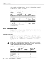
The RJ-45 modular connector has strain-relief functionality incorporated into the design of its
standard plastic connector.Table A-4 and Table A-5 list the pinouts and signals for the RJ-45 and
MII connectors.
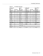
Table A-4
FEIP Port Adapter RJ-45 Connector Pinout
Note
Referring to the RJ-45 pinout in Table A-4, proper common-mode line terminations should
be used for the unused Category 5, UTP cable pairs 4/5 and 7/8. Common-mode termination reduces
the contributions to electromagnetic interference (EMI) and susceptibility to common-mode
sources. Wire pairs 4/5 and 7/8 are actively terminated in the RJ-45, 100BaseTX port circuitry in the
FEIP port adapter.
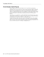
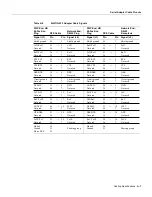
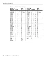
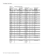
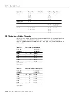
Table A-5
FEIP Port Adapter MII Connector Pinout
Pin
Description
1
Receive Data + (RxD+)
2
RxD–
3
Transmit Data + (TxD+)
6
TxD–
Pin
1
1. Any pins not indicated are not used.
In
Out
I/O
Description
14–17
–
Yes
–
Transmit Data (TxD)
12
Yes
–
–
Transmit Clock (Tx_CLK)
2
2. Tx_CLK and Rx_CLK are provided by the external transceiver.
11
–
Yes
–
Transmit Error (Tx_ER)
13
–
Yes
–
Transmit Enable (Tx_EN)
3
–
Yes
–
MII Data Clock (MDC)
4–7
Yes
–
–
Receive Data (RxD)
9
Yes
–
–
Receive Clock (Rx_CLK)
10
Yes
–
–
Receive Error (Rx_ER)
8
Yes
–
–
Receive Data Valid (Rx_DV)
18
Yes
–
–
Collision (COL)
19
Yes
–
–
Carrier Sense (CRS)
2
–
–
Yes
MII Data Input/Output (MDIO)
22–39
–
–
–
Common (ground)
1, 20, 21, 40
–
–
–
+5.0 volts (V)
Summary of Contents for TelePresence Server 7010
Page 10: ...x Cisco 7010 Hardware Installation and Maintenence ...
Page 14: ...iv Cisco 7010 Hardware Installation and Maintenance Document Conventions ...
Page 148: ...3 36 Cisco 7010 Hardware Installation and Maintenance Using the Flash Memory Card ...
Page 158: ...4 10 Cisco 7010 Hardware Installation and Maintenance Troubleshooting the Processor Subsystem ...
Page 242: ...5 84 Cisco 7010 Hardware Installation and Maintenance Replacing Internal Components ...
Page 258: ...A 16 Cisco 7010 Hardware Installation and Maintenance MIP Interface Cable Pinouts ...
Page 270: ...B 12 Cisco 7010 Hardware Installation and Maintenance Interface Processor LEDs ...
Page 274: ...C 4 Cisco 7000 Hardware Installation and Maintenance ...
Page 287: ...Index 13 ...


